The Domain panel contains the parameters defining the structure size (NX, NY, and NZ) in combination with the resolution (Voxel Length), as well as the Origin parameters, the Periodicity check boxes, the Center Domain button, and the Pore/Matrix Material and Matrix Density selection.
The internal representation of a structure in GeoDict consists of rectangular 3D arrays of cubes, hereafter called volume elements or voxels.
NX, NY, and NZ are the number (N) of voxels in X, Y and Z directions. The Voxel Length is the size of one voxel in the chosen units. Varying the values for NX, NY, and NZ has the effect of changing the size of the domain in the given direction.
Low values for the voxel length in combination with high values for NX, NY and NZ result in a higher resolution, but also in a higher computational time. After setting the values of NX, NY, and NZ, and Voxel Length, the physical structure size is automatically displayed in the chosen units (here µm).
Observe in the figures below how starting with NX=200, NY=200, NZ= 200 (200 x 200 x 200 µm3, at voxel length 1 µm), and decreasing the Voxel Length from 1 µm to 0.5 µm, has the effect of refining the structure by increasing the resolution but decreases the size of the volume to 100 x 100 x 100 µm3.
By setting NX=400, NY=400, NZ= 400, to restore the size of the volume to the original 200 x 200 x 200 µm3, the original structure is created at higher resolution.
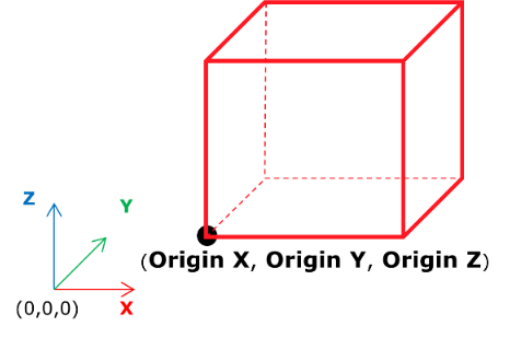
The Origin X, Origin Y, and Origin Z parameters, together with the Center Domain button, determine the placement of the structure in the physical space. Zero values for Origin X, Origin Y, and Origin Z mean that the point with (0, 0, 0) coordinates is located at the lower left corner of the structure.
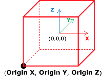
When clicking the Center Domain button, the (0, 0, 0)-point is set to the center of the structure as shown below.
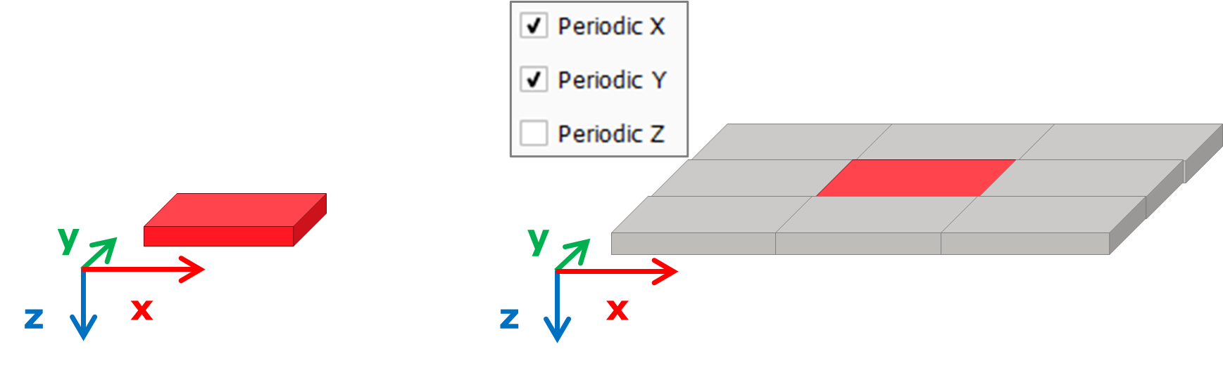
The periodicity of the paper structure is determined by checking or un-checking the Periodic X, Periodic Y, and Periodic Z boxes in one or several directions.
Periodicity has the effect that the fibers ending on one side of the domain reappear in the opposite side, so that when several domains with periodic fibers are combined, the structure emerges as a repetitive complex.
Know how! A warning message is displayed when trying to generate a periodic structure with fibers that are longer than the domain size, since they might overlap themselves.
An error message appears when trying to generate a periodic structure with Infinite fibers. To avoid this error, go to Fiber Options and remove the Infinite fibers or, alternatively, do not choose to generate with periodicity.
Observe the effect that checking or leaving unchecked the Periodic X and Periodic Y boxes has on the periodicity of a generated fibrous structure. View the paper structure in 3D Rendering and in 2D Cross-Section.
The effect is readily observed when repeating the sample structure with ProcessGeo (Model → ProcessGeo – Crop, Embed & Add Layers → Repeat: X-, Y-, Z- 400 voxels) and viewing it again in 2D View from the Z-direction.
Choose the material of the matrix around the fibers from the material selector.
When the default pore material (Air) is chosen, the fibers are embedded in empty pore space. When the chosen pore/matrix material is a solid, the density of this material can be entered or is directly taken from the GeoDict Material Database.
The color representing the pore/matrix material can be made visible (default is invisible rendering) and changed through the Color & Visibility tab in the GUI side bar on the right-hand side of GeoDict.