Flow Experiment
Flow Settings
The Flow Direction is fixed to From Inlet to Outlet.
The Flow Motion regime can be chosen as Creeping flow (Stokes) or Fast flow (Navier-Stokes) based on the flow velocity and the Reynolds number.
Inlet Material ID and Inlet Boundary Condition
Define the inlet of the flow by selecting the Inlet Material ID. For this, it is necessary that the inlet is marked with a different material ID. This can be easily done by selecting a voxel on the inlet area and using the Flood Fill Component Plane feature of the Voxel Selection tool. For an automatic recognition of Inlet phase it is advised to provide the information “Inlet” to the selected material ID.
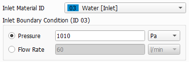
The Inlet Boundary Condition can be either set by prescribing the Pressure or the Flow Rate.
Outlet Material IDs
Define the outlet area of the flow by selecting the Outlet Material IDs. In cross flow setups multiple outflow areas must be selected. At each outflow area, set the local Pressure value.
Domain Boundary Conditions
The 3D model typically contains also the filter housing. In this case, flow will only occur inside of the filter housing and the domain boundary conditions do not apply. However, if the filter is symmetric, it is possible to reduce the computational cost by modelling only one half or one quarter of the filter. In these cases, the flow area will be open to one or two sides of the domain and one should select Symmetric boundary conditions for the flow at the domain boundary.
No-Slip means that the structure is encased in a solid wall at the domain boundary.
