Grid Options For The Non-Rectangular Grid
Basis Vectors
When Create Rectangular Grid is not checked, the three Basis Vectors can be defined freely. In the first row of the table, Basis Vector 1 is defined which belongs to the X-axis. Basis Vector 2 (in the second row) belongs to the Y-axis, and Basis Vector 3 (third row) belongs to the Z-axis. The first column contains the X-component, the Y-component is in the second column, and in the third column the Z-component is entered.
|
Important! The basis vectors must be linearly independent to span a volume in space, so an error message appears if this is not the case. 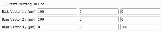  |

Domain
The domain options now differ from those available in the rectangular case. Since the unit cell might be non-orthogonal or rotated with respect to the GeoDict coordinate system, the domain containing the structure can no longer be described by numbers of unit cells in the coordinate directions. Instead, the size of the domain must be entered directly.
As it happened for the Rectangular Grid, the basis vectors define the size and shape of the unit cell and therefore the relation between succeeding unit cells. The effect of using non-orthogonal basis vectors is illustrated in the following figure by changing only one vector (Basis Vector 3). The domain size is set equally in each dimension to 200 µm.
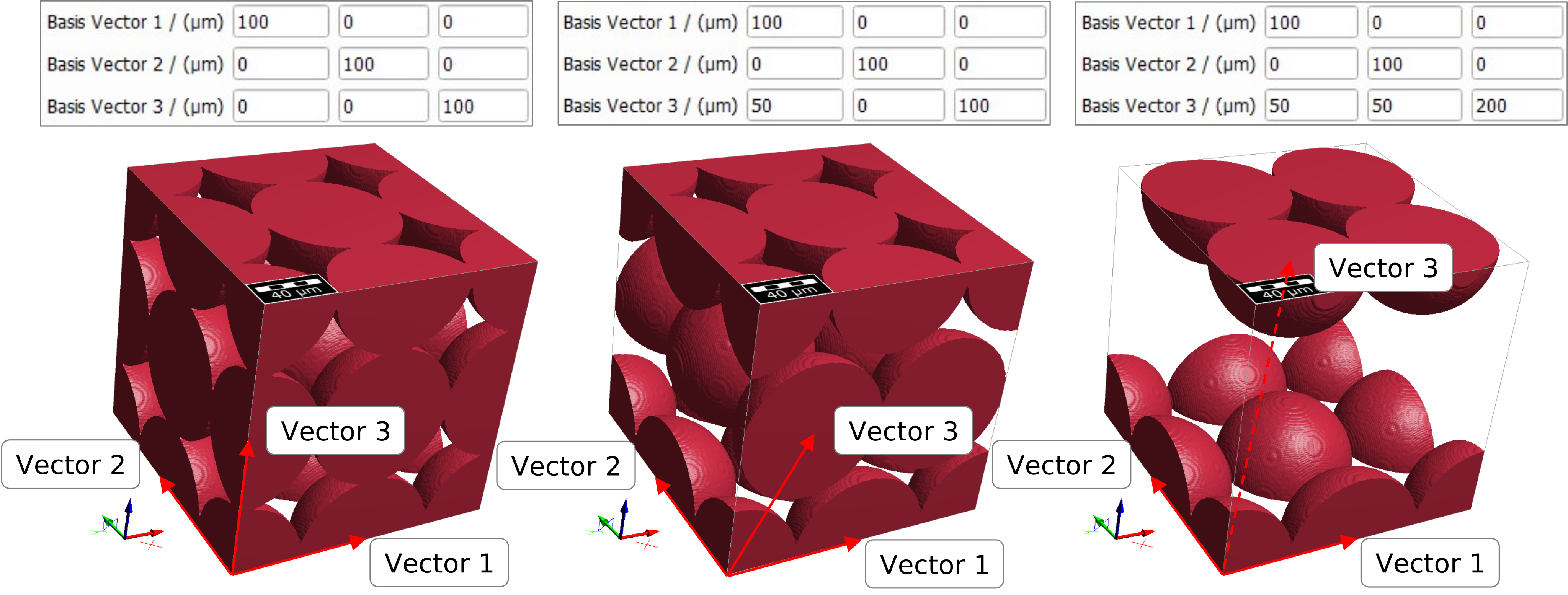
With the use of non-orthogonal basis vectors, the Body-Centered Cubic and Face-Centered Cubic grids can be generated with only one sphere per unit cell.
Lattices with this property are called Bravais lattices. Find out more about them here.
Voxel Length and Number
The Voxel Length sets the size of a voxel in the selected unit and, therefore, the resolution of the structure. Together with the domain length (Width (X), Length (Y), and Height (Z)) it will determine the values for the domain size in voxel, which are shown below (NX, NY, and NZ) and cannot be edited. It will also show the achieved domain size in metric units and the error compared to desired domain size (e.g. a width of 50 µm can not be fully resolved with 4 µm voxel length, the error is 2 µm in this case).
|
Note! Try to adjust the voxel length or the domain size to minimize the error. |

Select Pore Material
The material for the Pore / Matrix Material (ID 00) in the grid can be chosen in the Domain panel. The material(s) of the object(s) are set in the Objects in Unit Cell tab.
The pull-down menu gives access to selecting the desired material from the GeoDict Material Database. When none of the materials available in the database fit the preferred specifications, Manual should be chosen. Alternatively, a new material with the desired specifications can be added to the Material Database (see the Material Database handbook).

To match realistic material colors for visualization in a certain application, the default material colors can be changed through the Color & Visibility tab of the GUI sidebar. For more visualization options, see the Visualization handbook.
Overlap Behavior
In the generated grid, overlap between the objects might occur. This overlap can be handled in different ways.
By default, Resolve Overlap is enabled. With this option, the overlapping regions are assigned to the materials of the objects which are in contact. This leads to a more realistic structure.

Additionally checking Mark Contact Voxels allows to define a separate material for the contact areas. This means, for each overlapping object a one voxel thick layer is reassigned to the Contact Material. In this way, even contacting objects with the same material ID can be clearly distinguished.
|
Know how! Using Resolve Overlap needs more time to compute, therefore we recommend disabling this option for large structures where the information about the overlap is not relevant (e.g. for flow simulations). |

Alternatively, an Overlap Material can be selected for the regions where objects overlap.

