Slice Thickness Adjustment
In FIB-SEM images the slice thickness can be different for each slice. If the image provides information about the slice thickness, as is the case, e.g., for images taken by Zeiss machines, the Slice Thickness Adjustment can be applied on the image. Otherwise, NO slice thickness available is displayed at the top of the section.
In the following figure, observe how the different slice thicknesses are assigned to coordinates building a vector indicating slice thickness.
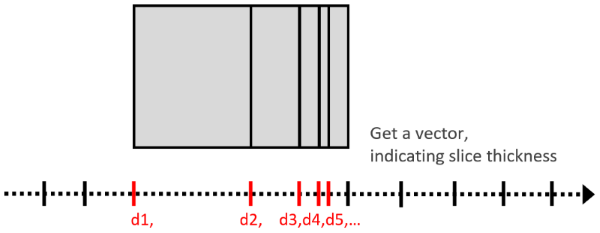
These vector entries must be provided with the considered image stack. Therefore, each image of the stack must have the ending “_z=…um” (unit must be in given in microns), where “…” must be replaced by the corresponding coordinate, e.g., image_001_z=1.0um.tif, image_002_z=2.1um.tif, image_003_z=3.3um.tif, …. FIB-SEM image stacks from Zeiss machines follow this name-scheme.
The slice thickness is adjusted by interpolating gray value images between the given Z-slices to fit the given distance.
If Use X/Y Voxel Length is checked, the distance between the resulting Z-slices is set equal to the voxel length in the X- and Y-direction. Otherwise, enter the desired Z-Distance in nm.
For the gray value Interpolation, select between Linear and Nearest Neighbor.
Click Apply to apply the Slice Thickness Adjustment to the image.
In the following example, the slice thickness between the single images is approx. 2 µm, while the voxel length in X- and Y-direction is 1 µm.
Thus, checking Use X/Y Voxel Length and clicking Apply leads to 256 slices instead of 129 and the image is stretched in Z-direction.