Example: Matrix Damage
ElastoDict-Deformations can be used to determine matrix damage in a composite model. In this example, E-Glass fibers are combined with an epoxy matrix. The structure used for this example is generated with FiberGeo.
Select Deformations from the pull-down menu in the ElastoDict module section.
Model damage for the matrix material
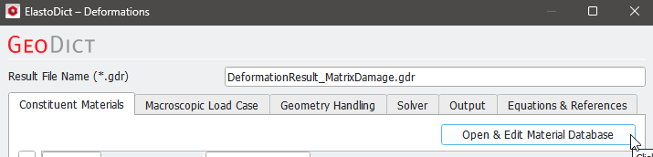
In this example, the matrix material is supposed to take damage under a tensile load. Therefore we want to add a damage model to the material Epoxy (3501-6). You can directly change the predefined material stored in the Material Database or, as is recommended, define a new material by copying the existing one and add the damage model. Therefore, open the Material Database by either clicking on the corresponding button in the main UI
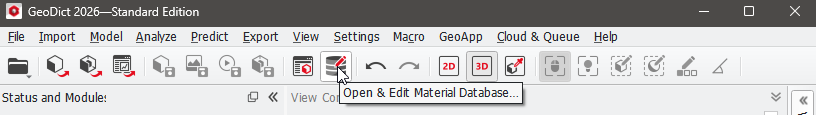
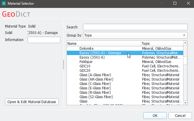
or by clicking on Open & Edit Material Database:
In the Material Database dialog first click Epoxy (3501-6) and then on Copy...
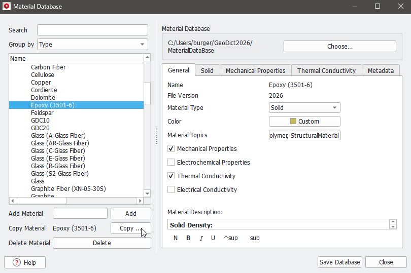
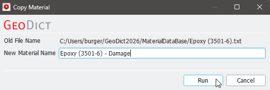
Now, you can choose a name for the copy, e.g., Epoxy (3501-6) - Damage, and click on Run.
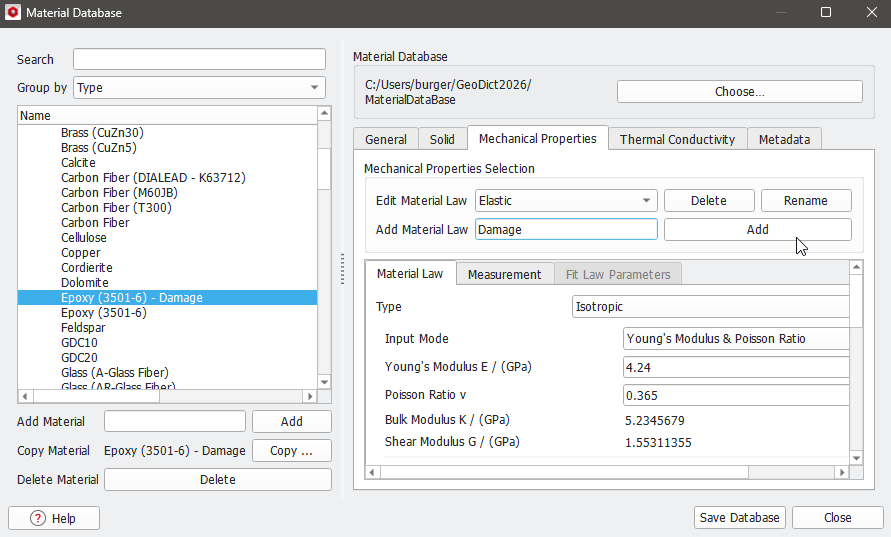
Now, you can choose the new material Epoxy (3501-6) - Damage in the Material Database and define damage by Adding a Material Law under the Mechanical Properties tab. Therefore, enter the name of the new law (Damage for this example) into the dialog box and click on Add.
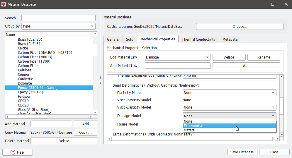
The material law Damage is visible under Edit Material Law automatically and you can choose which damage law you want to use by expanding the dropdown menu under Damage Model. For this example, we choose the Exponential damage model.
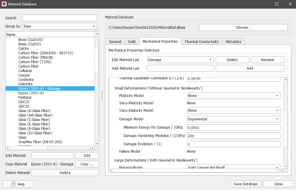
After choosing the damage model, the material parameters have to be defined. For this example the exponential damage is defined by the following parameters:
After all material changes are done, click on Save Database to save these changes to your local Material Database and Close to close the editor. Now, you can choose the newly defined material under the Constituent Materials tab in the Deformations Edit dialog.
Under the Mechanical Properties tab choose Damage for Material Law and activate the Exponential Damage by checking the Exponential checkbox.
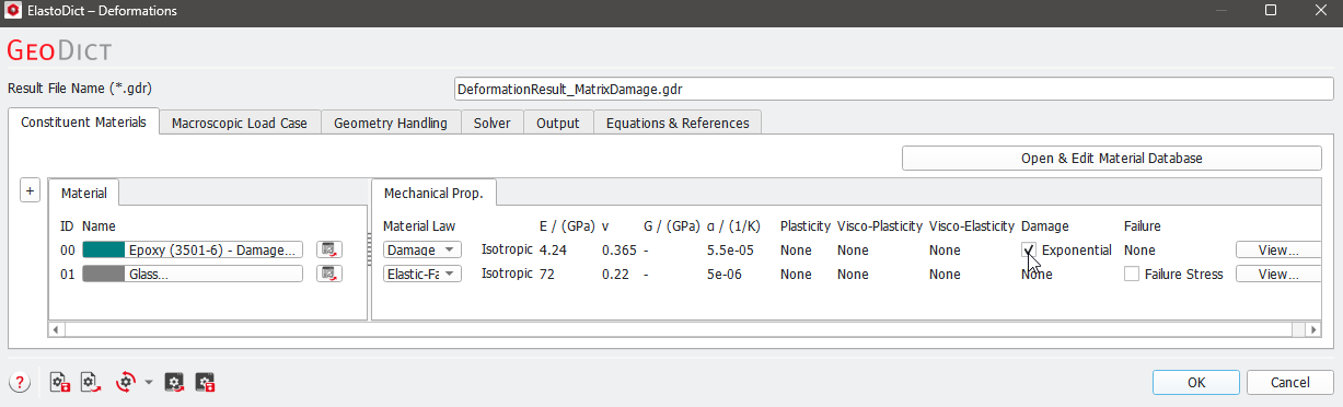
For the glass fibers choose the Glass with the Elastic-Failure (E-Glass) material model. The Failure Stress option for Glass can additionally be enabled, although it is not necessary for this example.
Set up all other parameters
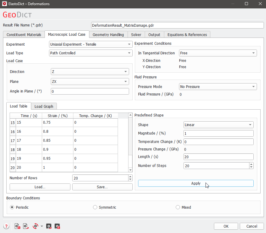
Under the Macroscopic Load Case tab set the experiment to Uniaxial Experiment - Tensile. A maximal strain of 1% is applied in 20 steps, therefore
- choose Predefined Shape,
- set Magnitude to 1%,
- set the Length to 20s,
- and the Number of Steps to 20.
- Click apply to set the load in the Load Table.
For damage simulations, it is useful to choose small steps for the load (here, 0.05% strain per step).
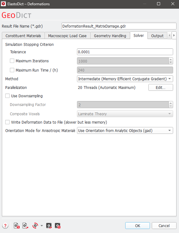
Under the Geometry Handling and the Solver tabs, keep the default settings. In particular, keep the Tolerance at the default of 0.0001 since a high accuracy is important, especially for simulations with damage.
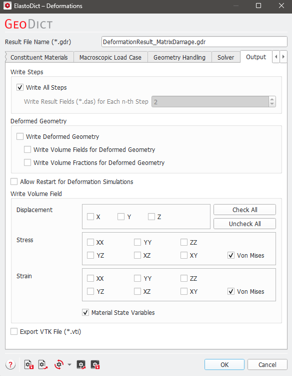
Under the Output tab, uncheck Write Deformed Geometry since generating the deformed geometries takes additional computation time and the deformed geometries are not relevant in most damage simulations (since the strain at the point of failure is often very low).
Analogously, writing volume fields might take a significant amount of disk space and time, depending on the size of the structure. Some disk-space and computational time is saved by unchecking stress, strain, and displacement fields which do not need to be visualized. Therefore, keep only the volume fields Stress - Von Mises and Strain – Von Mises and the Material State Variables (containing the damage variable in this example).
Click OK to close the Options dialog and start the simulation by clicking Run in the GeoDict GUI main screen.
Results
After the simulation is finished, the result file is opened automatically in the Result Viewer at the Results - Report subtab.
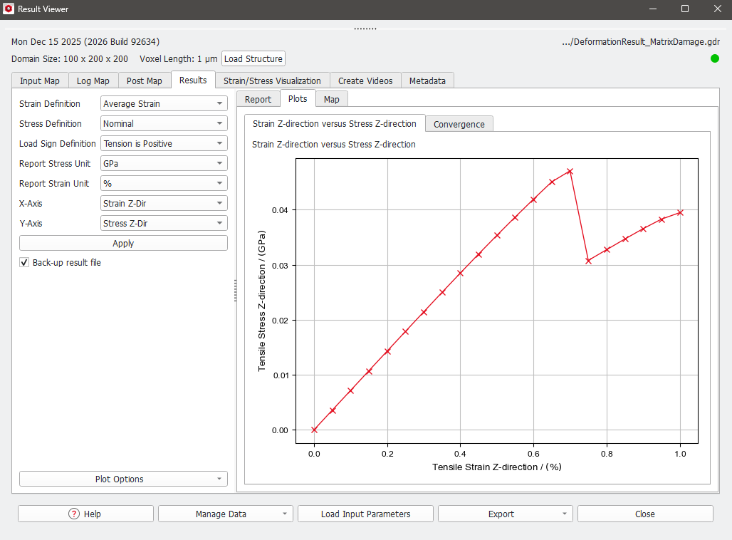
Under the Results - Plots subtab, the results of the deformation during the time series experiment are plotted as Stress-Strain chart (X-Axis: Strain Z-Dir; Y-Axis: Stress Z-Dir). Increasing damage leads to decreasing stiffness on the geometry.
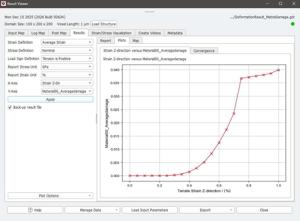
Choose Material00_Damage for the Y-Axis and click Apply… to plot the average matrix damage in the the matrix material (0 is no damage, 1 is maximal damage).
As shown in the plot below, the average damage rises steadily until the point of failure, which is indicated by the drop in the stress-strain curve at a strain of 0.75% in the upper image. After failure the damage continues to increase slightly.
Under the Strain/Stress Visualization tab volume fields for specific Time Steps can be loaded. Therefore, selected the desired time step from the pull-down menu (here, the point of failure at 0.75% Strain and 15s is selected) and load the Solution File by clicking Load.
After clicking on Load a new dialog opens with all available volume fields listed. Check the Volume Fields to be loaded and visualized. In this example von Mises Strain, von Mises Stress and Damage are available. The numbers 0 in Damage_0 stand for the Material IDs to which the volume field belongs.
Click OK to load the components.
In 2D and 3D Rendering, a color bar appears to the right (default position) during the visualization of the result file, indicating the value range of the selected component.
Further visualization parameters can be set under the Volume Field tab, in the Visualization panel above the Visualization Area. For more information, please refer to chapter Visualization.
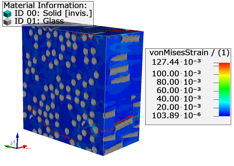 |
The highest strain can be observed at cracks. There, the stiffness of the matrix material is lowered due to the damage, which leads to high strain values and low stress values. |
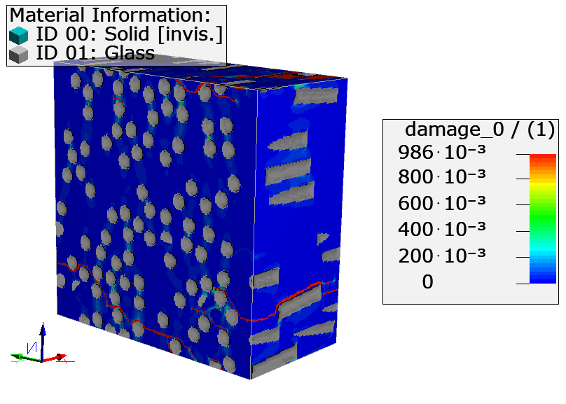 |
When damage is visualized, it is recommended to set the Data Range in the Color Map dialog to Min/Max or manually to a minimal value of 0.0 and a maximal value of 1.0 (see also screenshot on the next page). Then, the fully damaged areas are clearly visible.
|
The crack in the material can be best visualized with the Transparency option for the volume field. For this, set the transparency as shown in the screenshot below: Choose low values (e.g., 0.2) for low damage values (in this example, for damage values lower than 0.75), and high values (1, which means no transparency) for high damage values.