Example: Plastic Deformation
This UMAT included with GeoDict is used to simulate plastic deformation.
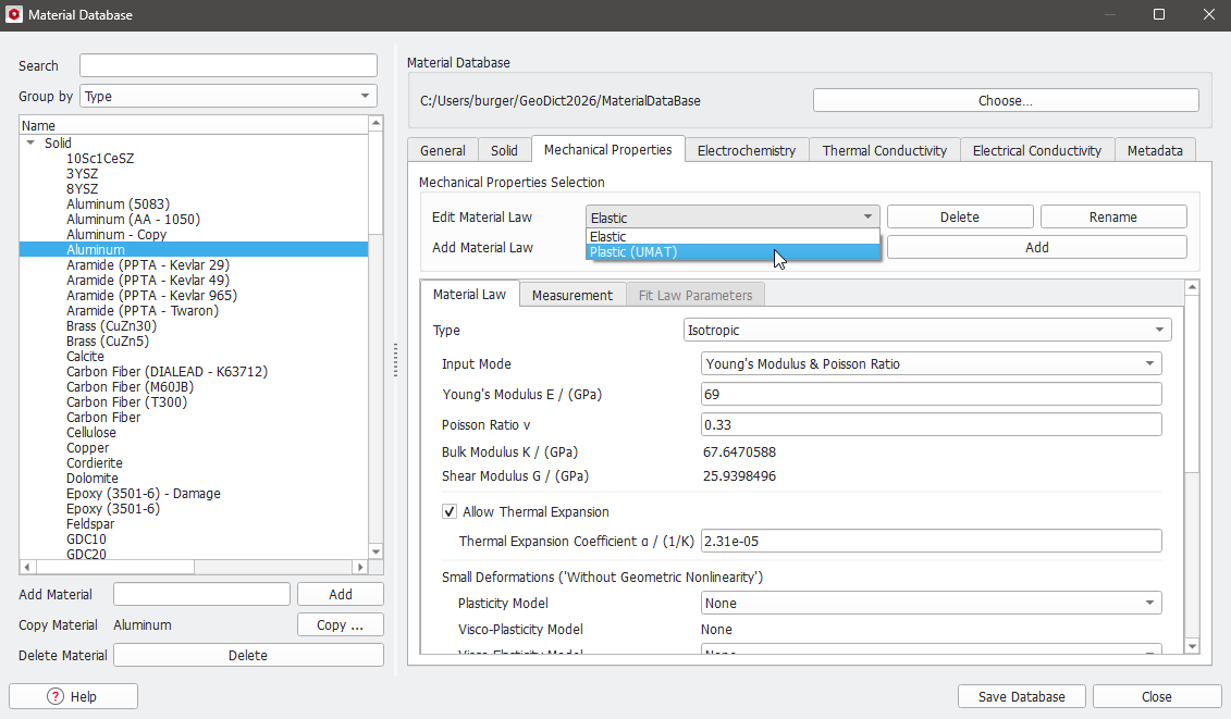
In the GeoDict Material Database, the UMAT IsotropicMisesPlasticity.f is contained in the database entry for Aluminum and appropriate parameters are already defined when choosing Plastic (UMAT) and Type - UMAT under the Law tab.
Besides the linear parameters (Young’s Modulus E; Poisson Ratio ν), it includes a piecewise linear hardening curve that was entered beforehand under the Mechanical Properties – Material Law - Material Parameters tab.
The plastic deformation of aluminum can be simulated in GeoDict using a solid block (generated through Model → ProcessGeo → Empty & Invert Structure → Create Empty Structure, 1x1x1 voxels, and then, Model → ProcessGeo → Empty & Invert Structure → Invert Structure).
|
Note! Generally, it is recommended to check the material behavior on small structures. If only a single constituent material must be investigated, a structure consisting of a single voxel is already enough. |

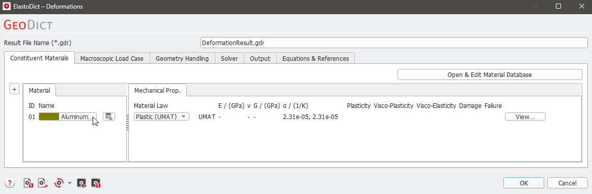
In the menu bar, select Settings → Select Constituent Materials. You can choose the material of the voxel by clicking on the button next to the ID number under the Material tab (see screenshot below). In the Material Selector dialog, select Aluminum from the list of available (Solid) constituent materials.
The color of the constituent material (Aluminum) may be changed via Settings → Color & Visibility Settings.
The plastic deformation can be examined during a cyclic stress experiment which can be set up in ElastoDict. In the menu bar, select Predict → ElastoDict.
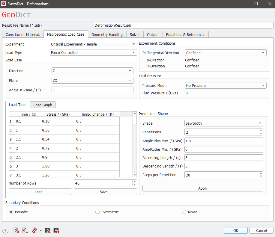
In the ElastoDict section, select Deformations and click the Edit… button. In the Deformations dialog, choose to apply the load in Z-direction in a Uniaxial Experiment-Tensile, with Confined boundary conditions in tangential direction. Choose the Load Type as Force Controlled.
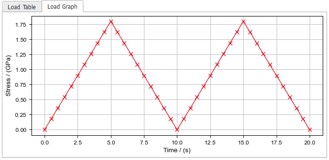
To define a cyclic load, use the Predefined Shape option to the right of the Load Table (screenshot below).
Choose the Shape as Sawtooth and the settings a shown in the screenshot.
By clicking Apply, the settings for the predefined shape are applied and the load table is defined automatically.
The graph of the load looks as follows:
Keep the default settings under the Geometry Handling tab.
Under the Solver tab, keep the default settings as well: Before GeoDict 2022, it was necessary to select the Memory Efficient (Neumann Series) when using nonlinear material laws, but this is no longer necessary.
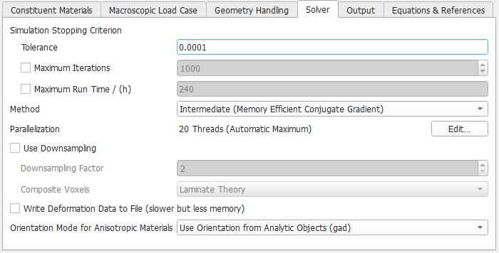
Under the Output tab, de-select Write Deformed Geometry. In this example, the simulation is done on a structure with only one voxel, and then, the deformed geometry does not provide useful information.
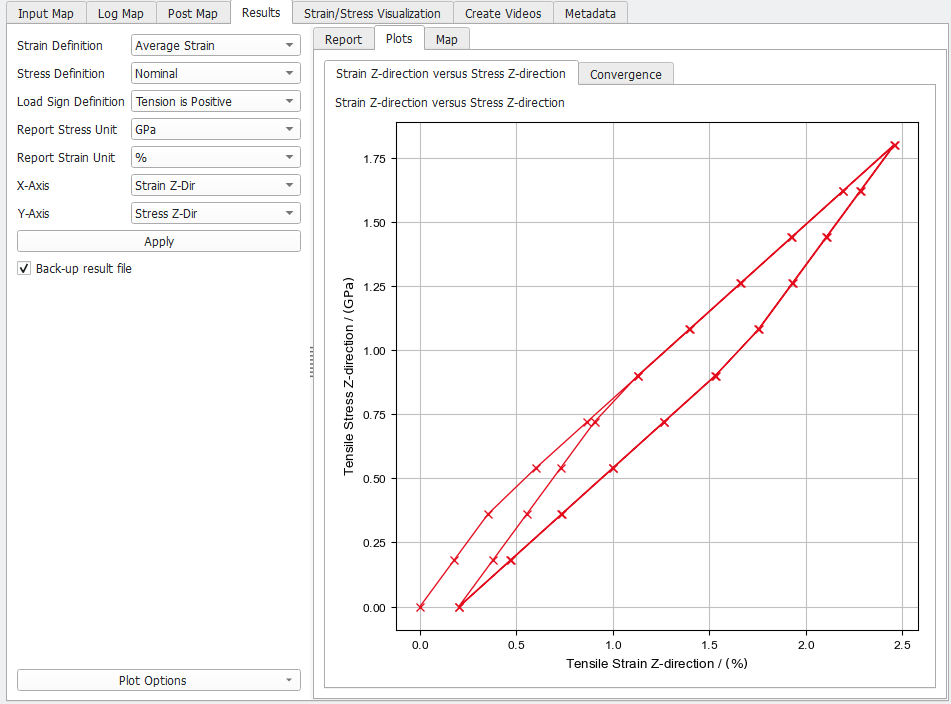
After running the ElastoDict - Deformations simulation, the Result Viewer of the result file (.gdr) opens at the Results tab. Under the Results - Plots subtab, choose to plot the Strain in Z-Direction (%) in the X-Axis against the resulting Stress in Z-Direction (GPa) in the Y-Axis, and click Apply….
Observe that the strain does not return to zero after the first load cycle and the plastic deformation remains in the material.