Filter Clogging
During the filtration process, particles are deposited on the structure. This is reflected in the simulation by changing the 3D structure model after each batch. The new structure consists of the filter material plus the deposited particles. Large particles, that are resolved in the voxel grid, will simply add solid grid cells to the structure. However, many particles are comparable in size to the voxel length, or even smaller. In this case, they will not completely fill a grid cell. Therefore, the simulation has to track the (dust filled) Volume Fractions of each voxel and model flow and filtration properties according to the state of the voxel.
FilterDict offers different models to handle this:
- In Resolved simulations, all voxels are treated as either empty or solid for flow and filtration, and the volume fractions are simply used to decide whether a voxel is empty or solid.
- In Unresolved or Mixed resolution simulations, partially filled voxels are modeled as porous voxels for flow and filtration. A Flow Resistivity model determines how the flow resistivity depends on the locally deposited volume fraction.
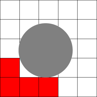
In the examples below, the initial structure consists of empty pores (white in the illustrations below) and full solid (red) voxels. During the filtration process, particles (gray) are caught in the filter. In Filter Element simulations, the original structure can already contain porous voxels.
Resolved Particles Simulation Mode
This model is only suitable if all particles diameters are larger than the voxel length.
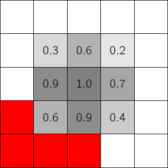
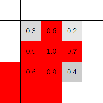
After each batch, the voxels with caught particles are analyzed. If the volume fraction in a voxel is higher than the Volume Fraction Threshold (default is 0.5), the voxel is set to solid. Otherwise, the voxel is considered as pore.
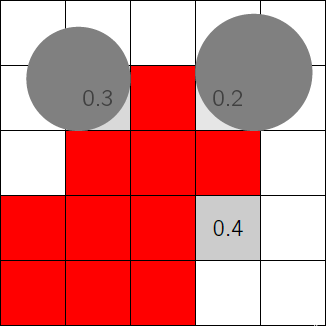
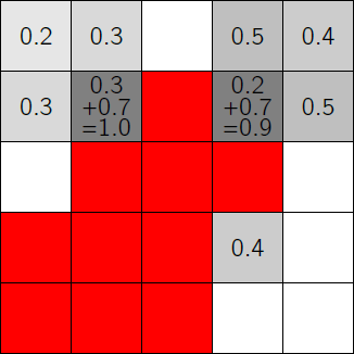
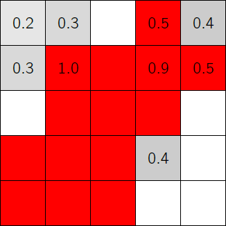
The volume fractions from succeeding batches are added. Under certain circumstances, the volume fraction of a voxel might exceed 1.
First Batch
 |
 |
 |
1. A large particle deposits on some solid voxels shown in red. |
2. Volume fractions shown for the corresponding voxels. |
3. New solid voxels appear when is larger than the Volume Fraction Threshold (here 0.5). |
Subsequent Batch
 |
 |
 |
4. Additional large particles deposit in the following batch. |
5. Volume fractions shown for the corresponding voxels. |
6. New solid voxels appear when is larger than the Volume Fraction threshold (here 0.5). |
Mixed/Unresolved Particles Simulation Mode
This model is suitable if there are at least some particle diameters smaller than the voxel length, or if all particle diameters are smaller than the voxel length.
In unresolved simulations, voxels may be porous. These voxels may contain captured particles or be made of porous filter material. Porous voxels have a flow resistivity depending on their volume fraction. Particles can only enter a voxel when its volume fraction is smaller than the Maximal Particle Packing Density .
Therefore, the Navier-Stokes-Brinkman equations (282) and (283) have to be used to determine the flow through the resulting structure. The flow resistivity is given as a function , where denotes the local solid volume fraction inside a voxel. Different options are available for the user to describe this function in the Constituent Materials tab.
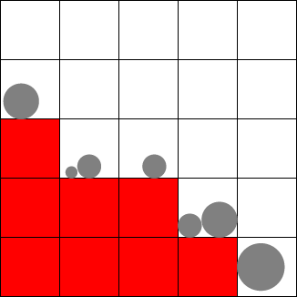
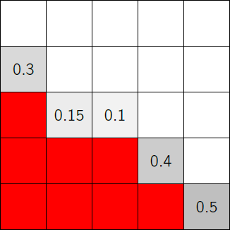
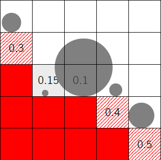
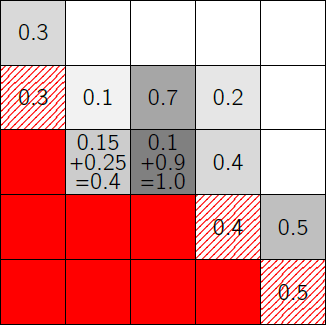
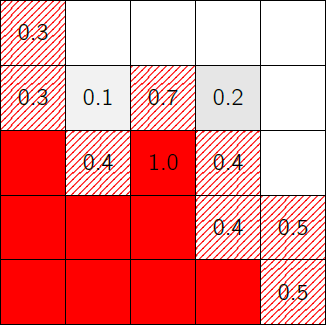
The figure below shows the process of small particles clogging the structure in mixed/unresolved simulation mode. Solid voxels (marked in red) will block flow and particles, as in the resolved mode. Partially filled voxels (shown in gray) will have an increased flow resistivity, and voxels with (shown in striped red) will block particles from entering.
Also in the mixed/unresolved simulation mode, some voxels may turn into solids, if . is always larger than and by default set to . Thus, when a voxel is completely filled with dust particles, no flow is possible any more.
First Batch
 |
 |
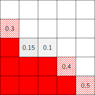 |
1. Particles deposit on some solid voxels shown in red. |
2. Volume fractions shown for the corresponding voxels. |
3. Voxels where is larger than the Maximal Particle Packing Density (here 0.3) become impassable for particles (shown in striped red). |
Subsequent Batch
 |
 |
 |
4. Additional particles deposit in the following batch. |
5. Volume fractions shown for the corresponding voxels. |
3. Voxels where is larger than the Maximal Particle Packing Density (here 0.3) become impassable for particles (shown in striped red). A new solid voxel appears where is larger than (here 1.0). |
During one batch, interaction between particles is not simulated. Thus, it is possible that particles from one batch overlap each other. A measure for this effect is the Volume Loss. A high value indicates that the number of overlapping particles is high. To avoid this, decrease the number of particles per batch.
