Report
The Report tab under the Results tab shows the computed results.
It starts with the Permeability (3x3) tensor. Below the Permeability tensor, the Error bound tensor (or Tolerance tensor) is located. This special tensor indicates the accuracy of the off-diagonal permeability entries. If the color code in the table is yellow or red, it might be a good idea to repeat the simulation and consider the Flow & tangential permeability in the stopping criterion.
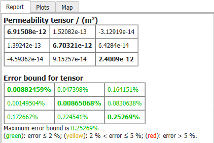
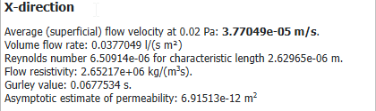
Below, for each selected Computational Direction, detailed results are shown:
- Pressure drop / flow velocity: the determined result (pressure drop or flow velocity) is always shown in bold face.
- Volume flow rate: either prescribed as boundary condition or computed in the simulation.
- Reynolds number: estimated with the given characteristic length. You can change the characteristic length in the post-processing options on the left.
- Flow resistivity: derived from the determined permeability.
- Gurley value: derived from the determined permeability.
- Asymptotic estimate of pressure: the asymptotic result predicted by the Error Bound stopping criterion
Information about the convergence of the iterative solver is also displayed for each selected computation direction: iterations, runtime, memory usage, and applied stopping criterion.
In the last line the total runtime and total memory usage are given. Here, not only the resources used by the flow solver are taken into account, but also the time needed for the solver initialization and writing of the result files, and the additional RAM needed by GeoDict. Thus, even if only one flow direction is computed, the total runtime and total memory values are usually higher than the solver specific values.
Post-Processing
As described here, the computation of the permeability requires that the reference length is defined correctly. By default, the permeability is computed under the assumption that the porous media fills the whole 3D domain. If the domain contains outflow or inflow regions, you can adjust the length here by setting the appropriate Media Thickness in the post-processing panel on the left of the report. The Media Thickness X corresponds to the symbol in (363) , and similar for the other space directions.
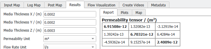
You can also change the Flow Rate Unit or the Permeability Unit - this will simply change the unit in which the results are reported.
You can also change how the Characteristic Length used in the calculation of the Reynolds number is determined. You can find further information on the Characteristic Length here.
Click Apply to change the Report. Changing the media thickness will change permeability, Reynolds number, and flow resistivity in the Results-Report and the Results-Map according to the new length for each direction. Changing the characteristic length with change the Reynolds number.
|
Important! Note that after clicking Apply, the result file changes and is not the original simulation result file anymore! If Back-up result file is checked, the original *.gdr file is saved in the result folder and can be restored at any time. |