Solid Oxide Electrode Generation
The Solid Oxide Electrode Generation app uses stochastic geometric modeling to generate three-phase microstructures (2 solids and 1 pore phase) typically observed for SOFC / SOEC electrodes. It generates two independent Gaussian random fields (GRF) to facilitate a bi-gaussian random field. Find more information about Gaussian Random fields in GrainGeo - Generate Gaussian Random Fields. This two-dimensional field is thresholded into three phases according to the specified volume fractions and contact angles, where the latter determine the wetting behavior of the phases. The approach is based on work of Marmet et al., 2023.

|
Modules needed to run this GeoApp:
FiberGeo or GrainGeo
|
Parameters
Click Edit to open the Solid Oxide Electrode Generation Parameters dialog.
Enter a Result File Name for the generated result file (*.gdr) and the corresponding result folder.
The parameters are organized in groups.
 Generate Gaussian Random Field
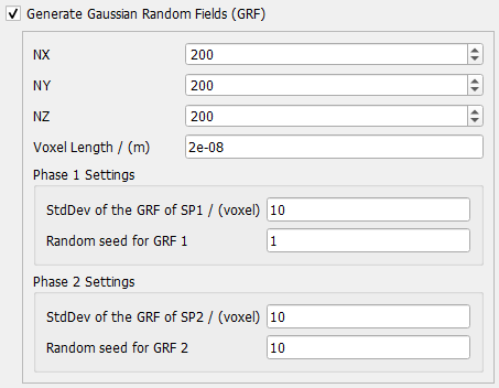
Check Generate Gaussian Random Fields to generate two new Gaussian random fields (GRF).
Define the domain size for the solid oxide electrode. These are also applied to the two GRFs. The domain size is given by the number of voxels in X-, Y- and Z-direction (NX, NY and NZ) and the Voxel Length in m.
Standard deviation (StdDev) and Random seed can be different for the two Gaussian random field phases and are defined in the two Phase Settings panels. Higher values for standard deviation lead to larger pores. Changing the random seed creates a different random field but with the same statistical properties.
The mean value for the GRFs is always set to 0.
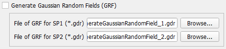
If rerunning the app for the same volume dimensions and the same random fields, uncheck Generate Gaussian Random Fields and browse for the two GRF result files in the solid oxide electrode result folder. They are loaded and analyzed for the new electrode generation. If not already present, they are copied into the result folder for the current electrode generation.
By using the same GRF for different solid volume fractions, compositions of phase 1 and 2, as well as contact angles between the phases, large parameter studies can be done quickly and highly computational efficient.
|
Material Phases
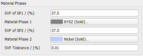
The two GRFs represent two solid phases. Each phase has its own solid volume fraction (SVF of SP1 and SP2) for the resulting electrode. Note that the sum of the two solid phases must be less than 100%. The remaining percentage (100 - SVF of SP1 - SVF of SP2) specifies the porosity of the electrode structure.
Click on the material box for Material Phase 1 or Phase 2 to define the materials for the two phases.
The solid volume fraction tolerance (SVF Tolerance) specifies how close the generation process approximates the target values.
|
Change Expert Settings
Check Change Expert Settings to edit additional settings.
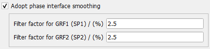
Adopt phase interface smoothing: applies a Gaussian filter to the previously generated or loaded GRFs. This way, the phase boundaries created by thresholding are smoothed.
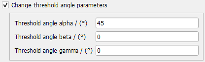
Change threshold angle parameters: The thresholding angles between the three resulting phases can be set. Their setting differentiates the two solid phases between wetting and non-wetting behavior. The values are optional and have commonly used defaults (neutral wetting behavior). See Marmet et al., 2023 for further details. If not checked, the default values are used.
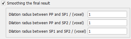
Smoothing of the final result: To dilute the boundary between two phases, a smoothing based on voxels is applied. Dilation is used to coat neighboring voxels from another material. Doing this vice-versa between two phases, the boundary is smoothed. For this purpose, the dilation between two of the three phases can be stated. Note that at least one pair of phases needs to have a dilation radius >0 for any smoothing to commence. PP is pore phase, SP1 is solid phase 1 and SP2 is solid phase 2.
|
Algorithm
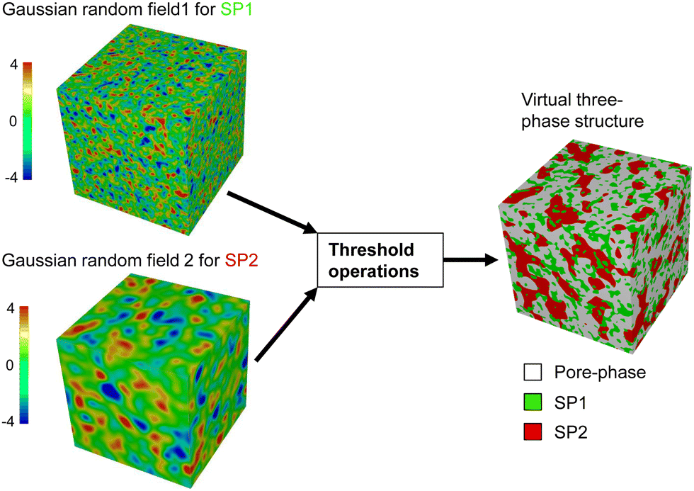
The figure below (see also Marmet et al., 2023, Figure 3) illustrates the virtual structure generation with pluri-Gaussian random fields. Two GRFs are combined with threshold operations to achieve three phases with defined phase volume fractions and wetting behavior.
|
Results
Clicking Run starts the solid oxide electrode generation.
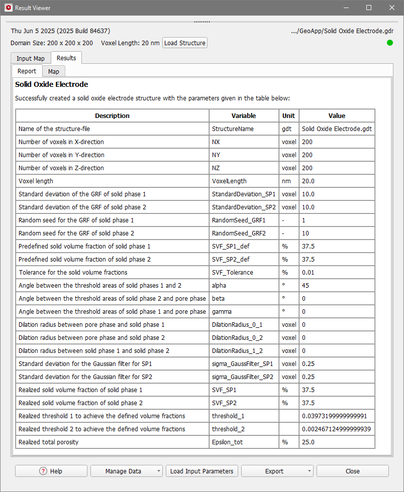
When the structure generation finishes, the Result Viewer of the result file (*.gdr) opens automatically.
The Results - Report tab displays a report about the resulting structure. The realized values here correspond to the created Gaussian random fields before they are combined. Thus, the final realized values may differ. The volume fractions of the material you can read from the volume fraction bar in the Statistics Section on the left of the GeoDict GUI.
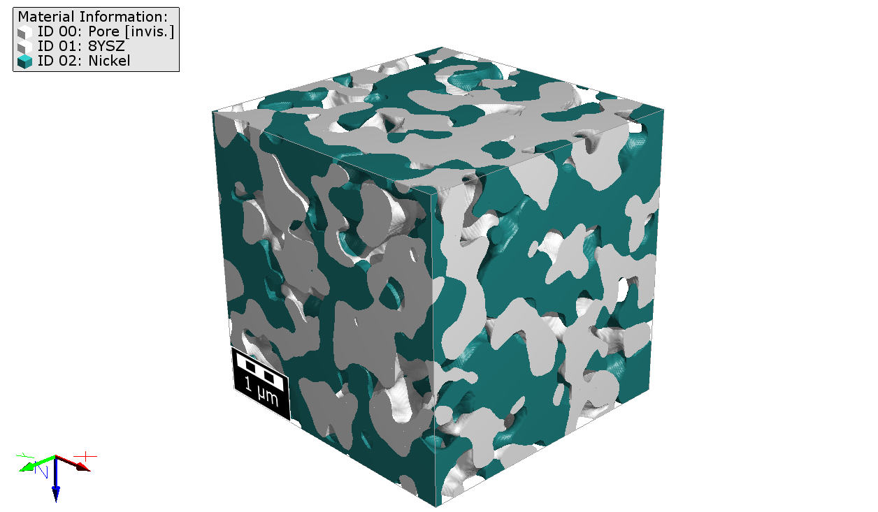
The generated solid state electrode structure is shown in the visualization area of GeoDict:
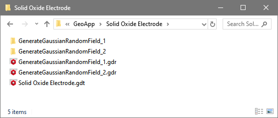
The result folder contains the GRFs and the electrode structure file.