For the Initial Particle Parameters, either choose to Create Particles according to the options below or Load Particles from File.
To Load Particles from a File, browse, select, and open an existing *.gpp (GeoDict particle parameters) file. This file may origin from a previous AddiDict simulation or can be generated using GeoDict’s Python API. See the Automation user guide for further information. Additionally, you can define a Random Seed and the Particle Start Velocity. If Fluid Velocity is chosen, every particle starts with the local velocity of the fluid flow. If Given Velocity is chosen, every particle starts with the entered velocity. The given velocity can be applied in all three directions or only in Z-direction.
When you select Create Particles, the parameters for the creation of the particles can be defined in detail.
Particle Start Position
Select one of the following Particle Start Position types. The default start position is the Inflow Plane.
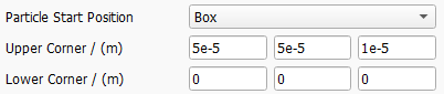
If Box is chosen as Particle Start Position, two opposite corners of a rectangular box must be defined. All particle start positions will then be inside of this box.
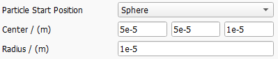
If Sphere is chosen as Particle Start Position, the center and radius of the sphere must be defined. All particle start positions will then be inside of this sphere.
An arbitrary location can be set by selecting Chosen Material IDs as Particle Start Position.
For example, by using GadGeo, various objects can be added into the inflow area. Those objects can be assigned to the same fluid material as the surrounding pore space, so they only serve as markers of a certain area (see picture below).
If this area ID is now chosen as Start Position Material ID, all particles start in this area. It is possible to mark several areas in this way and/or to choose several IDs as starting areas.
If Everywhere is chosen as Particle Start Position, particles may start everywhere in the pore space of the structure. .
Particle Positioning Weights
Particle start positions are scattered randomly inside the defined Particle Start Position area or volume.
By default, those positions are uniformly distributed. Be aware that a spatially Uniform placement in the inlet will lead to an increased particle concentration in areas with low fluid velocity, e.g., in proximity to a surface or a walls.
If Velocity is selected, the starting probability is based on the local fluid velocity. Selecting this option will lead to a uniform particle concentration in the inflow.
If Distance is selected, the starting probabiliy is based on the distance from the next solid object. This will lead to higher particle numbers in the core flow, while there will be less particles starting next to the surface.
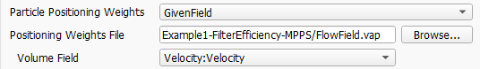
With GivenField, it is possible to load an arbitrary 3D field of scalar values to define the starting probability. For example, it is possible to load the flow field of a previous computation and select the velocity or one of its components.
Random Seed
Particles to be transported are placed randomly in the Particle Start Position volume and may move randomly due to Brownian motion. The Random Seed sets the seed of the underlying random number generator. The same random seed produces identical results, whereas results with different random seeds are similar but not identical.
Particle Start Velocity
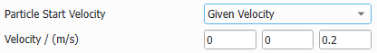
Select either Fluid Velocity (the default option, which was used until GeoDict 2025) or Given Velocity as the Particle Start Velocity.
With the first option, particles begin moving with the fluid velocity at their start position.
With the second option, all particles start with the same user-defined velocity.
Particle Start Time
The Particle Start Time defines when the particles are released to the flow. Through the Edit button, the particle start time can be set to be Constant, or to follow one of these distributions: Uniformly in interval, Gaussian, or an arbitrary Probability Distribution.
For particles to be released following a Gaussian distribution, define the Mean Value, the Standard Deviation, and the Distribution Width of the distribution. The particle release times are centered on the Mean Value and vary according to the Standard Deviation.
The value in Distribution Width corresponds to the range on both sides of the mean value limiting the particle release time value that is accepted. A Distribution Width of 1 means that release time values may deviate only from -1 s to +1 s from the given Mean Value.
The parameters must be set so that no negative values are possible. For example, a release time mean value of 1 s and a distribution width of 2 s would lead to an error message appearing, as the time could reach a value less than zero.
Check Cut-Off Distribution to restrict the start times selected by the random number generator to the interval defined by the distribution bounds. Otherwise, random numbers outside of this interval are set to the distribution bounds.
With Probability Distribution, a discrete distribution for the particle release time can be defined. The table describes the probability (Count Probability) of a release time taking a certain Value.
The Probability Sum of all Count Probabilities defined in the table needs to be equal to one. Use the Normalize button to scale the Count Probabilities accordingly. The Number of Rows can be increased or decreased to enter the desired number of release time Values and their Count Probability, between 0 and 1. The buttons Load and Save allow you to load a previously defined probability distribution and save the current one for later use.
Number of Particles
The Number of Particles determines the number of particles inserted into the geometry over the entire simulation period.
Particle End Position
Three options are available for the Particle End Position:
Particles can also leave the simulation when they hit a voxel with one of the defined Material IDs, i.e., they are not considered anymore in the computation.
Particles can stop moving and leave the simulation if the Particle Displacement is larger than a predefined maximum value. This option can be used to, e.g., simulate a long channel (like in a catalytic converter) that is much longer in flow direction compared to the other two directions. By defining a maximum displacement, the simulation can be run on a much shorter channel in flow direction using periodic boundary conditions.