Constituent Materials
On the top of this tab, select if the Particle Resolution is Resolved or Mixed.
Choose Resolved if all particles are larger than the current voxel length, and Mixed (unresolved) if some particles are smaller than the current voxel length. For further explanation, see the Filter Clogging page.
Temperature
The Temperature for the filtration process is selectable in Kelvin (K), Celsius (°C), and Fahrenheit (°F). The chosen temperature may change the density and viscosity values of the fluid during the simulation, if those are defined to be temperature-dependent in the material database. Furthermore, if the Brownian motion of the particles is included in the simulation, it determines the strength of the Brownian motion through equation (290) .

Fluid Density and Viscosity
FilterDict uses single-phase flow simulations. It is not possible to run a flow simulation if two fluids are present in the structure. If multiple fluids are present in the structure, you may click Set all Fluids to… and select one fluid for the simulation.
The selected fluid is also displayed in the drop-down menu in the Material subtab behind Use. The density and the dynamic viscosity of this fluid are shown under the Fluid Density/Viscosity subtab.
If a fluid from the GeoDict Material Database is used, the values for Density and Dynamic Viscosity are taken from the database and may depend on the given Temperature value. Select Manual as fluid material to enter parameter values manually.

To add materials to the database, use the Open & Edit Material Database button. More information on editing, expanding, and using the GeoDict Material Database is available in the Material Database user guide.
Filter Media Permeability
Under the Permeability subtab, enter the permeability of porous materials present in the structure. As long as there are only fluid and solid materials present in the structure, no parameters are needed here:
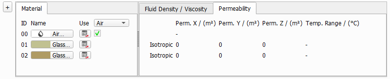
For porous materials, choose if the material is Isotropic or Anisotropic. In the isotropic case, the permeability is the same in all space directions. In the anisotropic case, enter a different permeability for each spacial direction.

You can select and change a material by clicking on the material button.
|
Know how! The anisotropic permeability is always aligned with the coordinate system, not with the orientation of the filter media. Therefore, it is often the best choice to select Isotropic and use the through-plane permeability of the flat sheet material, as this is the permeability most relevant to the flow direction. |

Local Clogging and Flow Resistivity
If the unresolved particle model is selected, the Local Clogging and Flow Resistivity tab will also be available.
Unresolved particles will create porous voxels when deposited into the 3D structure. In those voxels, flow is still possible, but experiences an increased flow resistivity. In the Local Clogging and Flow Resistivity tab, the relation between the dust volume fraction inside of a voxel and the flow resistivity must be defined. This tab is only available for unresolved simulations, because in the Resolved case all voxels are treated as either empty or solid.
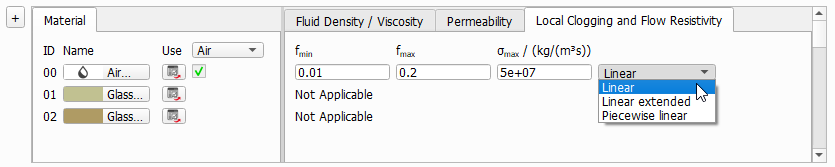
The flow resistivity depends on the values for , , and , which must be defined for every material of the structure which can be filled by dust particles during the simulation, i.e., inside of the fluid (where the filter cake will form) and in all porous layers.
|
Note! It is necessary to set these parameters for the fluid material, although this might be unintuitive at first glance. Be aware that the parameters set for the fluid material describe the behavior of the filter cake because the filter cake consists of partially dust-filled voxels of the fluid domain. |

|
Note! It is not possible to use different fluids in a structure, but it is possible to use different material IDs with the same fluid. This option is useful, when the filter cake should have different properties depending on its location in the structure. |
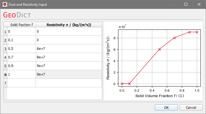
Three different models are available to define the function : Linear, Linear extended, and Piecewise linear.
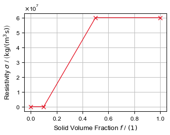
 Linear Extended
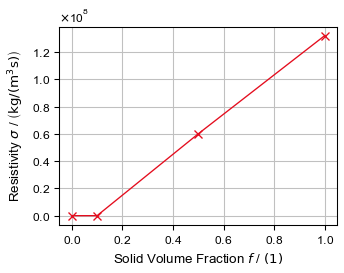
|
Know how! You can upscale the results of a fully resolved filter media simulation to determine these input parameters. In the Report tab of a Filter Media - Filter Lifetime command, the Filter Clogging Analysis computes parameters that can be used as input here. Use the reported Cake Filtration values as and of the fluid phase and the reported Depth Filtration values as and of the porous filter material. |
