Flow Experiment
On the Flow Experiment tab, define where and how fast the flow motion is directed and set the boundary conditions.
Flow Settings
The Flow Direction inside the structure will always be From Inlet to Outlet.
The Flow Motion can either be creeping or fast flow. In the creeping flow case, the Stokes equations are solved to determine the flow field. If fast flow is chosen, the Navier-Stokes equations are solved to determine the flow field.
As the Stokes equation is a simplification of the Navier-Stokes equation, choosing Fast Flow (Navier-Stokes-Brinkman) will give correct results also in the case of slow, creeping flow. Solving the Navier-Stokes equations is computationally more expensive than solving the Stokes equations, so it is advisable to choose Creeping Flow (Stokes-Brinkman) whenever justified.
Inlet Material ID and Inlet Boundary Condition
Select the desired Inlet Material ID from the pull-down menu. If one of the material IDs additionally has the Information Inlet or Inflow, it is preselected by default.
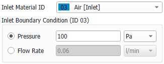
Then, either define the average Pressure at the inlet or the Flow Rate at the inlet for the experiment.
|
Know how! You can add additional information to a material ID while editing the materials either in the Constituent Materials tab or in the Constituent Materials dialog available by selecting Settings → Select Constituent Materials from the menu bar in GeoDict. Click on the material ID to open the Material Selector and enter the information on the left. |

Outlet Material IDs and Outlet Boundary Conditions
As Outlet Material IDs more than one material ID can be selected. If a material ID additionally has the Information Outlet or Outflow, it is preselected by default.
Set the Pressure for at least one outlet ID. It must be smaller than at the inlet, since pressure decreases from inlet to outlet. From the pull-down menus different units can be selected. If more than one outlet ID is selected, it is possible to define the Flow Rate for all outlet IDs but one.
If all outlet IDs are defined by Flow Rate, an error message appears.
|
Conditions for Inlet and Outlet Definition.
If the inlet or outlet are not set correctly, then an error message appears when starting the simulation |
Domain Boundary Conditions
Set the boundary conditions in all directions to be Periodic, Symmetric, or No-Slip. More details on these settings can be found here.
The domain boundary conditions do not apply to the selected inlet and outlet areas. They apply to all fluid voxels at the domain boundaries that are neither inlet nor outlet. In cases where the 3D structure model contains the complete casing or housing, no such fluid voxels at the domain boundary exist, and the selection has no effect.
If the simulation is done on one half or one quarter of a symmetric 3D structure, Symmetric boundary conditions must be used.