|
Navigation: GeoDict 2026 - User Guide > Introduction > Graphical User Interface > Menu Bar > Settings |
Scroll |
Settings
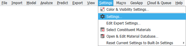
Selecting Settings… from the Settings menu opens the Settings dialog to modify the general preferences or properties when working with GeoDict. The dialog contains the General, Parallelization, Statistics, and Job Queue tabs. They contain a collection of overall settings that are applied to any GeoDict session.
Clicking Save & Close at the bottom of the dialog results in carrying out the modifications and closing the dialog. Select Cancel to discard the modifications entered in the dialog.
General tab

The first option under the General tab allows to define the Color Scheme of GeoDict. You can explicitly set it to Light or Dark mode, or use the System Scheme, which you can select in the system settings.
|

Control the size of the fonts used in the GUI when opening GeoDict (GUI Start-Up Font Size).  For example, increasing the GUI Start-Up Font Size results in the display of a larger font overall in the GUI.
|
GeoDict automatically stores a copy of the previous structure, before applying any changes to it, until the Memory for Undo is filled up.  This allows to quickly undo any changes using the undo function in the toolbar.  The disadvantage of keeping a copy of the last structure is that some runtime and hard disk space is required for saving the structures. Thus, it can be disabled by setting the Memory for Undo to 0 MiB. |
If Check for GeoDict Updates is checked, GeoDict will automatically search if updates are available (requires internet connection) and print a message if an update is found.  GeoDict will not automatically download or install those updates.
|

In the I/O (input/output) options panel, define how many days the log files should be kept. In the log files the events happening while running GeoDict are recorded, as well as debug outputs.
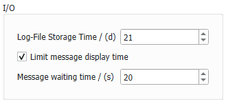 Also, define whether the time a warning message is displayed should be limited, and the time of the limitation in seconds. After the entered time has passed, the message is closed automatically. If 0 is selected, pop-up messages are not shown at all. However, pop-up messages are collected in the Notifications panel at the bottom, except for messages that ask for the confirmation of your choice (e.g., when Quitting GeoDict). |

In the Text Editor panel, set which text editor will be opened automatically when editing macros and other editable files. Click Browse to search and set the path to the location where the executable for the favorite text editor is located.  For a list of text editor recommendations refer to the GeoPy Scripting chapter. |
The last two options set the timeout options for floating license users only. Define after how many hours the Floater Release Timeout will be triggered. Then, all non-required floaters are freed and are available for other users. This is especially useful if many long-running computations are performed. The same behavior occurs when pressing the Release Floaters button in the progress bar during a simulation run.  The Idle Timeout triggers if after the defined hours no computation or user interaction was made. Then, all floaters, including the GeoDict-Base floater, are freed and available for other users. It is possible to re-acquire the freed floaters when returning to the GeoDict application in the then opening dialog. For both options, if 0 is entered as value, the corresponding option is disabled. |
Parallelization tab
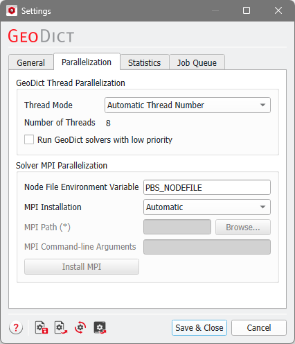
 GeoDict Thread Parallelization
In the GeoDict Thread Parallelization panel set the number of parallel processes (threads) GeoDict should use, e.g., for the visualization, for the image processing, and for the structure generation.
It is possible to set the Thread Mode to Max. Thread Number which equals the Number of CPUs the machine has. When not all available CPUs of the computer should be used, for example to allow other users to work simultaneously on the same machine or to improve the performance of other programs, the number of used parallel processes can be limited by setting a Manual Thread Number.  Choosing Automatic Thread Number uses the maximum number of cores, if up to eight cores are available. If more than eight cores are available, the maximum of eight and the number of available cores divided by two is used. For example, if the machine has 12 cores available, automatic thread number takes the maximum of 8 and 12/2=6 which is 8. Check Run GeoDict solvers with low priority to make the system more responsive when working interactively while a GeoDict solver (e.g., LIR or SimpleFFT) is running. |
For cluster computations, set the environment variable that holds the location of the node file, i.e., the file that contains the list of assigned compute nodes. For MPI parallel computations, set the path to the MPI Installation that should be used for the parallelization. Select Automatic to look automatically for MPI installations. 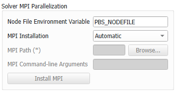 For more information, refer to the High Performance Computing chapter. |
Statistics tab
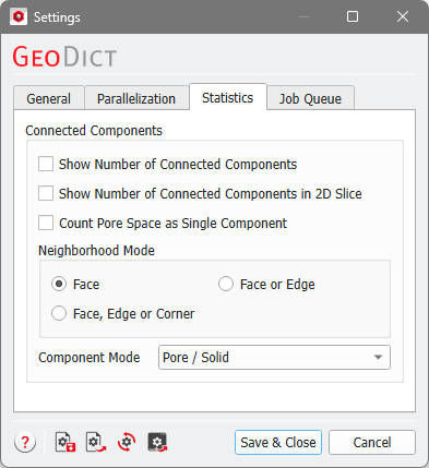
A connected component is defined as a complete set of connected voxels with respect to the chosen neighborhood mode and component mode. Checking Show Number of Connected Components or Show Number of Connected Components in 2D Slice, and clicking OK, adds the number of Components to the Statistics section in the Status section. If the pore space is divided by the structure into several parts, it can be counted as one connected component with Count Pore Space as Single Component checked. The pore space does not count as an object and does not add to the number of Objects. As an example, a simple periodic structure model containing 10 spheres is shown. At the corners, it is the same gray sphere that disappears and reappears on the other side. Two red spheres are also cut in half. They disappear and reappear in Z-direction. Three of the red spheres overlap and one of the red spheres touches a gray sphere. The number of GAD Objects in 3D is 10, but the number of GAD Objects in the shown 2D slice (Slice 126 in X-direction) is only 4 (2 gray and 2 red spheres. The pore space is not counted as object. Now, see how the connected components in 3D and 2D are counted when checking Show number of Connected Components and Show Number of Connected Components in 2D Slice. Neighborhood Mode and Component Mode define criteria for the connectivity of the components and are explained below. For this example, we choose Face as Neighborhood Mode, which means that two voxels are connected if they share a voxel face. As Component Mode we choose Pore / Solid, so that solid voxels can form a component independent of their Material ID. The number of Objects 3D and 2D are the same as before. Connected components in the 2D slice shown above are 4 (1 gray sphere + 1 red sphere + 1 [1 red sphere+1 gray sphere] component + 1 pore space). Connected components in 3D are 8 (3 gray spheres + 3 red spheres + 1 [3 red spheres+1 gray sphere] component + pore space). The example structure shown is periodic, thus, objects that end on one side of the domain and reappear on the opposite side are counted as being the same connected component. Periodicity of the domain is saved in the structure file and can be edited through GadGeo → Edit Domain (see the GadGeo chapter for more information). This might change the number of components, e.g., if GAD objects lie outside of the domain that is non-periodic. When changing to a periodic domain the objects are then placed inside the domain and counted for the number of components. |
The Neighborhood Mode defines if two voxels are connected (and belong, depending on the component mode, to the same connected component) or not. The different Neighborhood Modes are explained using this example.  Two voxels can be connected through faces, edges, and vertices (corners). Voxels that share a face, do also share edges and corners, as you can observe for the red and the blue voxel. The blue and the green voxel share an edge and the corner points of this edge. Finally, the blue and the yellow voxel share only one vertex (corner point). Thus, checking Face is more restrictive than choosing Face or Edge, and this is more limiting than selecting Face, Edge, or Vertex. When choosing the Neighborhood Mode Face only the red and the blue voxel are connected. When choosing Face or Edge the red and the blue voxel and the blue and the green voxel are connected. Finally, if Face, Edge, or Vertex is chosen, the red and the blue voxel, the blue and the green voxel and the blue and the yellow voxel are connected. |
For structures with more than one material, selecting Pore / Solid from the Component Mode pull-down menu determines whether the components are considered connected or not, based on being (empty) pore voxels (background) or solid voxels (structure), regardless of their Material ID. When selecting Material ID, it is the Mterial ID of the voxels that determines whether the components are considered connected or unconnected. In the following examples, the neighborhood mode is set to face.
|
Job Queue tab
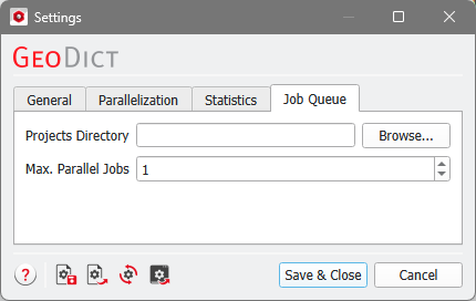
Browse for a Projects Directory to save the results of Job system runs and set the number of Max. Parallel Jobs.
Find out more about the Job Queue settings here in the Job Queue chapter.
©2026 created by Math2Market GmbH / Imprint / Privacy Policy
