Options
Clicking the Options’ Edit… button opens the Sinter & Crystallization options dialog to enter the desired parameters. Clicking OK closes the dialog and returns to the GrainGeo section. Clicking Generate starts the sintering process.
A structure containing GAD information must be in memory.
General Parameters
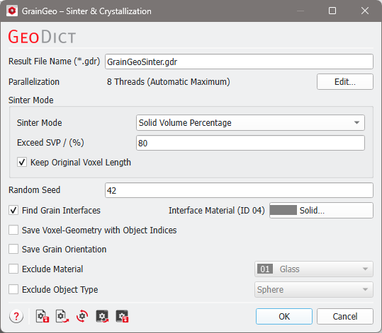
 Result File Name
At the top of the Sinter & Crystallization dialog, the name for the files containing the generation results can be entered in the Result File Name (*.gdr) box. The default name can be kept, or a new name can be chosen fitting the current project.
|
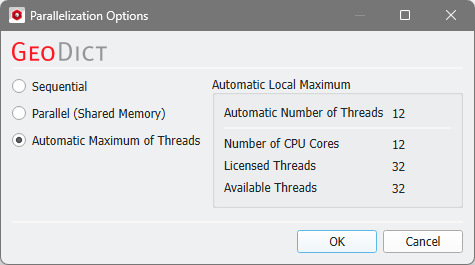
Parallelization
Control how many threads are used for the computation. Parallelization is possible if your license and hardware allow it.
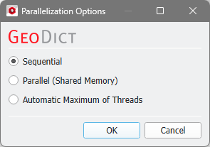
The Parallelization Options dialog opens when clicking the Edit button and you can choose between Sequential, Parallel (Shared Memory), or Automatic Maximum of Threads.
Selecting Sequential will not apply parallelization and only one thread is used for the computation.
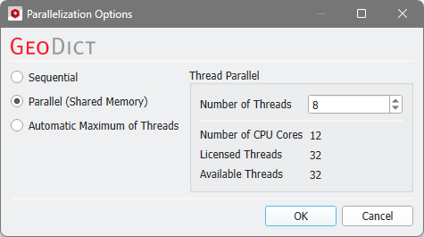
When Parallel (Shared Memory) is selected, the Number of Threads can be entered. Below, the Number of CPU Cores that the current machine has, the maximum number of Licensed Threads and the number of those licensed threads that are available (Available Threads) are shown in the dialog. Of course, the maximal number of parallel processes you can use, is the smallest of those three numbers.
If Automatic Maximum of Threads is selected, the number of parallel processes is automatically selected for optimal speed, based on the CPU cores and licensed parallel processes.
The Automatic Local Maximum of processes is automatically selected, which is the minimum of Number of CPU Cores, Licensed Threads, and Available Threads.
|
Sinter Mode
In the Sinter Mode panel, several parameters can be entered to control the sintering process.
Two different stopping criteria for the sintering process can be selected from the Sinter Mode pull-down menu:
- Solid Volume Percentage: The sintering process continues until the desired Solid Volume Percentage is exceeded (Exceed SVP). For this mode, you can decide to keep the original voxel length.
- Shrinkage defines the percentage by which the structure is contracted in each direction.
Example for Exceed SVP
Observe the effect of increasing Exceed SVP from 20%, to 40% and then to 60%, when a structure made of convex polyhedrons is sintered.
|
Keep Original Voxel Length
By default, the structure’s original voxel length is kept (Keep Original Voxel Length), which enlarges the solids. Unchecking this option decreases the voxel length, while the number of voxels remains constant.
|
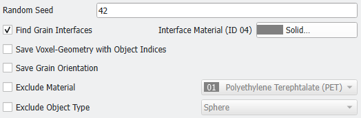
Specify Sintering
Specify which materials or object types should be sintered and if grain interfaces should be found or not.
Random Seed
Random Seed is a simulation parameter controlling the sequence in which objects are sintered. Thus, different random seeds lead to slightly different sintered structures. The random seed increases automatically with every sintering process.
|
Find Grain Interfaces
If Find Grain Interfaces is checked, the Interface Material of the sintered objects can be chosen from the GeoDict material database by clicking the button.
This results into a different material ID being assigned to the entire grain surface, including the interfaces with other objects. For example, later mechanical properties can be applied just to the grain interfaces for deformation or other elastic properties simulations with the ElastoDict module.
|
Save Voxel-Geometry with Object Indices
To save index image of the sintered grains in *.g32 format, check Save Voxel-Geometry with Object Indices. This file can be used, together with the structure, to track objects while computing, e.g., elastic properties with transversal isotropic or orthotropic constituent materials laws with the ElastoDict module.
If selected, the 3D result file can be loaded from the Result Viewer (Load (*.g32)).
|
Save Grain Orientation
To save the available information about the sintered grains in *.gof format, check Save Grain Orientation. This file can be used, together with the structure, to compute, e.g., elastic properties with transversal isotropic or orthotropic constituent materials laws with the ElastoDict module.
If selected, the 3D result file can be loaded from the Result Viewer (Load (*.gof)).
|
Exclude Material and Exclude Object Type
One object Material ID and/or one object type per structure can be excluded from the sintering process when checking Exclude Material or Exclude Object Type and choosing the Material ID or the object type name from the pull-down menus.
Exclude Material and Exclude Object Type can be simultaneously selected to exclude objects, that have a certain type or a certain material. For example, exclude all objects with Material ID 01 and additionally all spheres.
As a simplified example, observe the effect of sequentially excluding the material Polyamide (PA 66), here ID 02 in gray, or the Object Type sphere the during a sintering process of three object types made of three different materials.
|