|
Navigation: GeoDict 2026 - User Guide > Material Modeling > GridGeo > Perforated Foil |
Scroll |
Periodic Foil
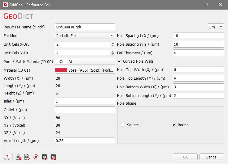

Periodic Foils are composed of one or multiple Unit Cells. One-unit cell consists of a flat piece of foil with one hole, which can be repeated periodically by setting the number of Unit Cells X-Dir. and Unit Cells Y-Dir. to the desired values. In the figure below, periodic foils consisting of one, four or twelve-unit cells are shown. |
The materials of the foil and the medium surrounding it can be chosen from the GeoDict material database by clicking the buttons Pore / Matrix Material (ID 00) and Material (ID 01). The pull-down menu gives access to selecting the desired material from the GeoDict Material Database. When none of the materials available in the database fit the preferred specifications, Manual should be chosen. Alternatively, a new material with the desired specifications can be added to the Material Database (see the Material Database chapter). 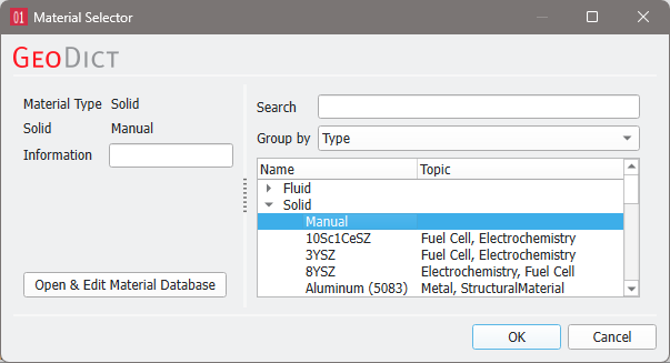 To match realistic material colors for visualization in a certain application, the default material colors can be changed through the Color & Visibility tab of the GUI sidebar. For more visualization options, see the Visualization chapter. |
The size of created structure in the chosen unit is displayed as Width (X), Length (Y), and Height (Z) and cannot be edited, but is affected by the Unit Cells and the Hole Spacing. |
Inlet and Outlet define the height of the empty area above and below the foil. The Inlet is in Z- direction, the Outlet is in Z+ direction. These parameters might be of interest for flow simulations on the foils, or when embedding them in other structures. |
The size of the created structure in voxels (NX, NY, and NZ) can also not be edited, but is determined by the size in units (Width (X), Length (Y), and Height (Z)) and the chosen Voxel Length. |
The Voxel Length determines the size of a voxel in the selected length unit and therefore the resolution of the structure. To evaluate the effect of choosing the number of Voxels per X-Unit Cell on the resolution of the structure, it is important that the 3D-structure mode is set to Box (select View → 3D Structure Renderer → Box). |
The parameters Hole Spacing in X and Hole Spacing in Y define the distance between subsequent hole centers, as shown in the figure below. Choosing a higher hole spacing value will increase the structure size. |
The Foil Thickness determines the height of the foil which influences the Height (Z) of the generated structure. |
The parameters defining the hole shape are explained in combination in the following figures. The main shape of the holes can be defined by selecting Round or Square for the Hole Shape. The hole dimensions at the top and bottom of the foil can be determined by setting Hole Top Width (X), Hole Top Length (Y), Hole Bottom Width (X) and Hole Bottom Length (Y). With these options, a large variety of hole shapes (e.g., straight or conical holes) is possible. Furthermore, the hole walls can be chosen to be curved (Curved Hole Walls). This option only has an effect if the hole has different sizes at the top and bottom. Below, find the examples from above, where the top and bottom of the hole have different size, but with Curved Hole Walls. |
©2026 created by Math2Market GmbH / Imprint / Privacy Policy