Shear
The Shear tool allows you to adjust volumes that have been distorted, as can happen in FIB-SEM images, for example.
For Shear Axis choose the shear direction and the coordinate that the Shear Angle is based on.
Click Apply to shear the structure with the current settings.
Shearing the image displaces each voxel in the shear direction (defined by the Shear Axis) upon consideration of the Shear Angle.
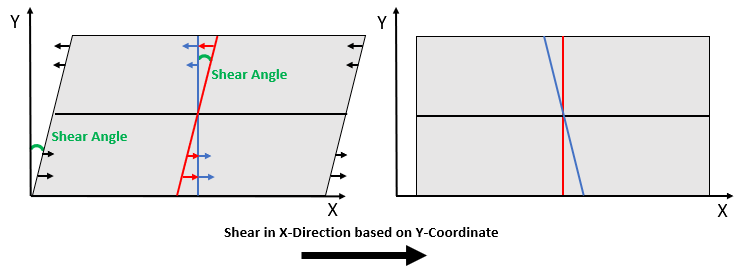
The figure below illustrates the process of handling a sheared image. In this example, the image is sheared in the X direction, resulting in a parallelogram. To correct the image, the Shear Axis must be defined as Shear in X-Direction based on Y-Coordinate. Then, the Shear Angle must be determined. After entering an angle, a yellow line will appear in the corresponding 2D slice. This line will become the new center line after clicking Apply. Gray values move as indicated by the arrow lengths below. For more information about the applied method, refer to Shear Mapping.
In the following example, the gray value image needs to be sheared in Z-direction based on Y-coordinate. The Shear Angle is set to 5°. Since Shear is selected as Overlay the resulting new center line is visualized with a yellow line.
|
Know how! You can Save your current settings for this tool as Start-Up Settings . The next time you process an image, these settings will be automatically loaded and filled into the parameter fields. You can also load the Built-In Default Settings available in GeoDict. If you change any settings and want to revert to your saved start-up settings, click the corresponding button to Load the Start-Up Settings . |

