The options in the Generation and Overlap Mode panel control the relative position among objects or of the structure currently in memory. It is possible to choose Allow Fiber Overlap, Without (Remove) Fiber Overlap, Prohibit Fiber Overlap, Use Isolation Distance, or Enforce Fiber Overlap.
If checking Create in Current Domain, additionally Prohibit Overlap with Current Structure appears. When choosing this option, the objects in the newly generated structure can intersect with each other but not with those of the already existing structure.
Know how! The algorithm under Allow Fiber Overlap is fast, especially for big structures and, in most cases, leads to excellent results.
If you choose Remove Fiber Overlap, the generation time may be longer when generating structures with high solid volume percentages. The objects are first positioned in the structure allowing overlap. Afterwards they are moved to remove overlap as good as possible.
Prohibit Fiber Overlap or Prohibit Overlap with Current Structure directly position the objects one after the other without overlap. This is fast for low densities, but may be very slow or even unfeasible when generating dense geometries since the positioning of new non overlapping objects might be geometrically impossible.
For the same reasons, with Use Isolation Distance, the generation time may be long, or the generation might be impossible depending on the chosen value for the isolation distance and the selected value for stopping criterion. Then, use the isolation distance option in the Remove Fiber Overlap dialog.
Generally, structures with overlapping objects can be used for processes in the pore space, as filtration and flow simulation. For simulations of mechanical properties, structures without overlap should be generated.
Checking Without (Remove) Fiber Overlap eliminates existing overlaps after the generation step.
Note! The statistical properties might change slightly after removing overlap.
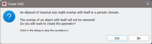
Overlaps can be removed from periodic structure models with objects smaller than the domain size or non-periodic structure models with arbitrary object sizes. In a periodic domain, objects which are longer than the domain might overlap with themselves. This type of overlap cannot be removed. In this case, a message appears:
The way in which the overlap removal occurs can be controlled through the Remove Overlap Options accessible via the Edit… button.
In the Remove Overlap Options dialog, the following parameters can be set:
Iterations: Defines after how many iterations the removal stops.
Iterations SVP Unchanged: The removal stops if the SVP (Solid Volume Percentage) remained unchanged during this number of iterations.
Overlap SVP / (%): Defines the final allowed Overlap SVP.
Allow Object Shifts: Check if shifting the objects should be an allowed operation for overlap removal. Define the Number of Shifts per iteration and the maximal Shift Distance in voxel per iteration.
Allow Object Rotations: Check if rotating the objects should be an allowed operation for removal. Define the maximal Number of Rotations allowed per iteration. Objects will be rotated in all directions, where the maximal rotation angle per iteration is one degree.
Allow Fiber Deformations: Check if bending fibers should be an allowed operation for overlap removal. Define the Maximum Bending Angle allowed between two segments. Each fiber consists of several segments. The center points of the segment connections are shifted in all directions, while the other shape parameters, as, e.g., fiber length and segment length are kept constant. The maximal point shift distance is the same as for the object shift. This option is only applied to fibers, as other objects do not consist of segments.
Distance Mode: The pull-down menu offers four options:
The objects can be Touching (distance zero).
Enter a maximal Defined Overlap allowed for the objects.
Enter a minimal Defined Isolation distance for the objects.
Avoid Contacts means a defined isolation of one voxel volume diagonal.
By selecting Use Isolation Distance, and inserting a positive value, the gaps between fibers have at least this preset distance.
Negative values for the isolation distance are useful to model paper structures with synthetic fibers that melt together during the lay down, or natural fibers that deform at touching points during the generation of the paper sheet. Then, the distance between the centers of the fibers is less than the sum of the two radii.
When the option Use Isolation Distance is set to negative values (e.g., -10 µm), the effect is that the fibers may overlap with maximally 10 µm (the negative isolation distance). Here, the effect is that some fibers penetrate other fibers and pass through them. The overlaps between fibers are assigned to a new Material ID and shown in a different color, which here is dark orange.
When choosing Prohibit Overlap with Current Structure (after checking Create in Current Domain), the fibers in the newly generated paper structure can intersect with each other but not with those of the already existing structure.
Observe this effect in a structure made of a woven screen over which a paper structure is generated. Whereas the paper fibers overlap with each other (in dark orange), they do not overlap with the pre-existing woven screen.
By checking Enforce Fiber Overlap, the structure’s fibers are required to join each other, forming a large connected component. This effect is obvious when the solid volume percentage (SVP) of the structure is low (here 10%), i.e., the fibers do not already form a connected component.

 Without (Remove) Fiber Overlap