|
Navigation: GeoDict 2026 - User Guide > Image Analysis > PoroDict > Percolation Path |
Scroll |
Options
At the top of the dialog, enter the Result File Name. The result files are saved in the chosen project folder (File → Choose Project Folder in the menu bar).
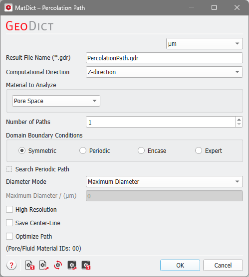

Set the direction of the paths by selecting the Computational Direction. 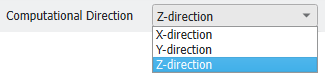 |
The algorithm searches for paths in the selected Material to Analyze, either Pore Space, All Solid Materials, Chosen Material, or a list of Chosen Material IDs. For your convenience, all Material IDs which denote pore space are shown at the bottom of the dialog. |
The number of percolation paths to be detected is set with the Number of Paths parameter. Then, the algorithm computes the n best percolation paths. |
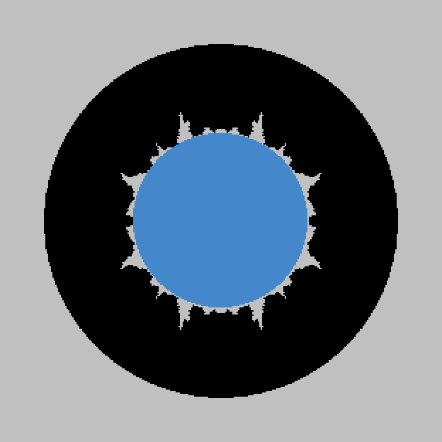
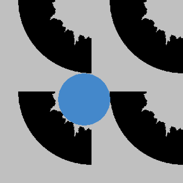
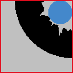
The diameters of pores and solids near the domain boundary are strongly influenced by the selected Domain Boundary Conditions. The boundary condition in the chosen computational direction is always set to symmetric, for the tangential boundaries you are free to choose other boundary conditions. The Domain Boundary Conditions can be chosen to be Symmetric, Periodic, Encase, or any combinations of those boundary conditions in all three directions with the choice of Expert. Choosing the appropriate boundary condition depends on the structure’s design. For example, imagine a structure with a cross-section as shown below.
For the three boundary condition options the resulting solid size is visualized in blue.
Check Expert to apply different boundary conditions for each direction. You can combine the three above mentioned boundary conditions independently for the directions. For example, the boundary conditions could be chosen to be Encase in X-direction, Symmetric in the Y-direction and Periodic in Z-direction. 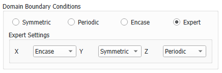 |
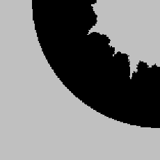
Search Periodic Path is only available for periodic boundary conditions. If checked, the Percolation Path is allowed to cross lateral periodic boundaries. Using this option increases the computation time. A periodic percolation path is not necessarily periodic in the computation direction. |
From the Diameter Mode pull-down menu, choose to detect percolation paths with the Maximum Diameter possible or Specify Maximum Diameter and enter a Maximum Diameter value below. |
To run the calculations in High Resolution might be useful when the path space is expected to be narrow. The standard algorithm computes distances directly on the voxel grid, i.e., when determining a pore size, only the distances from the center of a pore voxel to the center of a solid voxel are taken into account. High Resolution also takes the voxel surfaces and edges into account, so the computed distances correspond to the distance to the next surface or edge. The disadvantage of the High Resolution mode is that the calculation runtime and memory usage may increase by a factor of eight.
|

When Save Center-Line is checked, the results folder additionally contains *.gdt files with the centerline of each computed percolation path.  |
With Optimize Path, the length of the path is optimized after the calculation. This shortens the calculated path by removing voxel staircase artifacts: The algorithm works on the voxel structure and can therefore only find paths which run directly through connected voxels. Therefore, the default method might not always find the best path in structures with large open pores. In these cases, it is recommended to select Optimize Path (see the examples below). |
©2026 created by Math2Market GmbH / Imprint / Privacy Policy
