Filter Experiment
Under the Filter Experiment tab, enter the Mean Velocity of the fluid passing through the filter.
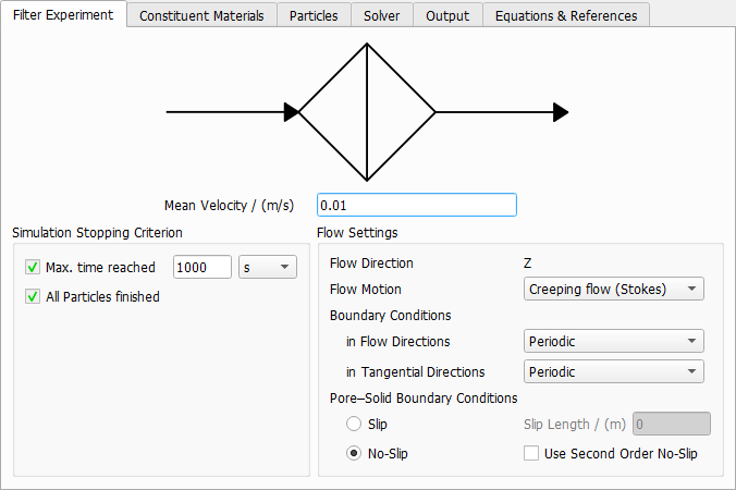
Simulation Stopping Criterion
Each particle trajectory is calculated by solving the equations (242) to (246) . Particle movement starts at and ends when the particle leaves the domain unfiltered, is filtered by the structure, or reaches the end of the given Max. time reached. This value is used to prevent exceptionally slow particles from increasing the simulation time and does not have a direct connection to the time of a measurement.
Particles which are still moving when the maximal time is reached are marked as time out particles.
Flow Settings
|
Important! The flow is always directed in Z-direction in FilterDict. |

Select the Flow Motion regime to be Creeping flow (Stokes) or Fast flow (Navier-Stokes) based on the flow velocity and the Reynolds number.
Select the Boundary Conditions in Flow Directions as Periodic or VinPout, which refers to velocity at inlet (Vin) and pressure at outlet (Pout). In Tangential Directions, select Periodic or Symmetric boundary conditions. For more information on these boundary conditions, please consult the FlowDict handbook of this User Guide.
The choices made for the flow boundary conditions in tangential directions also determine what happens when a particle reaches the domain boundary in one of the tangential directions. With Periodic boundary conditions, the particle will leave the domain and reappear on the opposite site. With Symmetric boundary conditions, a particle will be reflected at the domain boundary.
Pore-Solid Boundary Conditions
The Slip Length allows to include sliding effects in the flow simulation. Typically, the slip length is of the same order of magnitude as the mean free path of the fluid (which is e.g. 68 nm for air at ambient conditions) and can be neglected if this is much smaller than the voxel length. It becomes relevant when simulating air flow around nanofibers.
The default setting No-Slip corresponds to a flow velocity of zero along the structure.
Use Second Order No-Slip sets the tangential velocity to zero at the center of the voxel surfaces and uses a second order approximation of the velocity field. The first order setting, which is used when the box is left unchecked uses a linear approximation. Second Order No-Slip will increase precision when there are narrow pores in the structure.
Slip with a non-zero Slip Length simulates the sliding of the fluid along the solid, increasing the fluid mean flux and thus, the permeability of the structure. This option might be used when it is realistic for a given physical material. Currently, the same slip length value must be set for all materials in the structure.