Filter Experiment
Under the Filter Experiment tab, choose between a Single Pass or a Multi Pass experiment. For Single Pass, the experiment can be run at a Constant Flow Rate or at a Constant Pressure Drop (often used for membranes). For Multi Pass, choose between the standard test setup or a variant with an initially contaminated test reservoir.
When a method is selected, the setup is shown schematically in the dialog below the pull-down menu. Furthermore, the selected method will influence which options are available elsewhere in the Filter Lifetime dialog.
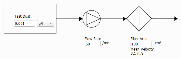
 Single Pass - Constant Flow Rate
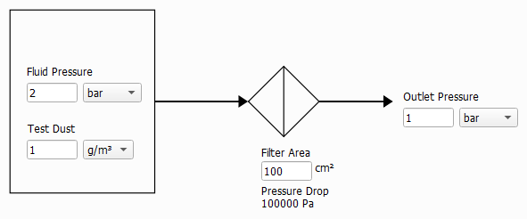
Single Pass - Constant Pressure Drop
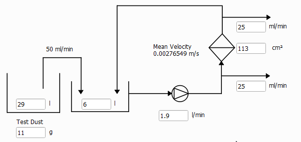
Multi Pass Test - [ISO 16889] Standard
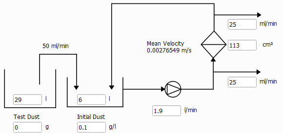
Multi Pass Test - Variant
Simulation Stopping Criterion
The simulation continues to run until one of the following criteria is reached:
- If Max. pressure drop increase is selected, the simulation stops if the initial pressure drop is increased by the given value. This option is not available if Single Pass - Constant Pressure Drop was selected.

- If Max. pressure drop is selected, the simulation stops if the given pressure drop is reached. This option is not available if Single Pass - Constant Pressure Drop was selected.

- If Max. flow rate decay is selected, the simulation stops when the flow rate falls below the given percentage (%) of the initial flow rate. This option is only available if Single Pass - Constant Pressure Drop was selected.

- If Max. time reached is selected, the simulation stops when the defined simulation time is reached.

- If Max. total deposited dust is selected, the simulation stops when the defined amount of deposited dust is reached.

- Multi Pass Test simulations always automatically stop when the Injection reservoir is empty.

- The simulation always automatically stops when the Inflow region is filled with particles. This is triggered when the first deposited particle reaches the inflow plane.

|
Note! Before GeoDict 2024 SP1, the simulation ran until an entering particle could not be placed anywhere in the inflow area. Thus, the inflow region got completely filled before the Inflow region filled state was reached. As a result, if the simulation ran until this criterion was reached, it showed a dense and compact filter cake. Since GeoDict 2024 SP1, the simulation stops when the first deposited particle reaches the inflow plane. In case of dendritic growth of the filter cake, this means that the simulation will stop earlier now, but also that the dendritic shape of the cake will be visible up to the end of the simulation. |

Flow Settings
In FilterDict, the Flow direction and, hence the filtration direction, is always the Z-direction.
The Flow Motion can either be creeping or fast flow. In the creeping flow case, the Stokes equations are solved to determine the flow field. If fast flow is chosen, the Navier-Stokes equations are solved to determine the flow field.
As the Stokes equation is a simplification of the Navier-Stokes equation, choosing Fast flow (Navier-Stokes) will give correct results also in the case of slow, creeping flow. Solving the Navier-Stokes equations is computationally more expensive than solving the Stokes equations, so it is advisable to choose Creeping flow (Stokes) whenever justified.
For Creeping flow (Stokes), Periodic, and Velocity in - Pressure out (VinPout) can be chosen as Boundary Condition in flow direction. VinPout cannot be chosen for a Single Pass – Constant Pressure Drop experiment.
For Fast Flow (Navier-Stokes), the boundary conditions in flow direction are set to Velocity in, Pressure out (VinPout) if Constant Flow Rate was chosen under the Filter Experiment tab, and set to Periodic if Constant Pressure Drop was chosen under the Filter Experiment tab.
In Tangential Directions, Periodic or Symmetric boundary conditions can be selected. For more information about the flow computation, please refer to the FlowDict handbook.
The choices made for the flow boundary conditions in tangential directions also determine what happens when a particle reaches the domain boundary in one of the tangential directions. With Periodic boundary conditions, the particle will leave the domain and reappear on the opposite site. With Symmetric boundary conditions, a particle will be reflected at the domain boundary.
Pore-Solid Boundary Conditions
The Slip Length allows to include sliding effects in the flow simulation. Typically, the slip length is of the same order of magnitude as the mean free path of the fluid (which is e.g. 68 nm for air at ambient conditions) and can be neglected if this is much smaller than the voxel length. It becomes relevant when simulating air flow around nanofibers.
The default setting No-Slip corresponds to a flow velocity of zero along the structure.
Use Second Order No-Slip sets the tangential velocity to zero at the center of the voxel surfaces and uses a second order approximation of the velocity field. The first order setting, which is used when the box is left unchecked uses a linear approximation. Second Order No-Slip will increase precision when there are narrow pores in the structure.
Slip with a non-zero Slip Length simulates the sliding of the fluid along the solid, increasing the fluid mean flux and thus, the permeability of the structure. This option might be used when it is realistic for a given physical material. Currently, the same slip length value must be set for all materials in the structure.