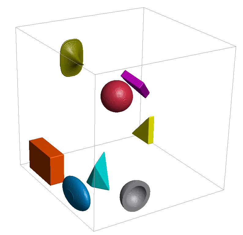
Several geometric shapes are available to create objects consisting of grains: spheres, hollow spheres, ellipsoids, and their generalized form of superquadric particles, rectangular boxes, triangular prisms, and planar and convex polyhedrons.
A sphere is defined by the position of its center and a diameter, given by the vector after the key Position and the value after the key Diameter (Radius).
The additional parameters Axis1 and Axis2 in the .gad file describe the orientation of the object. The third coordinate axis is not given as an additional parameter, but given as the cross product of Axis1 and Axis2, such that the three axes form a right hand system. The orientation of a sphere obviously does not change the visible 3D geometry, rather, it is used to model anisotropic material behavior. Those parameters cannot be modified through the user interface.
A hollow sphere is similar to a sphere, but has an inner diameter defining the void space inside the sphere, given by the value after the key InnerDiameter (or InnerRadius).
As for spheres, the additional parameters Axis1 and Axis2 in the .gad file describe the orientation of the object and cannot be modified through the user interface.
An ellipsoid is defined by its Center position, given by the vector after the key Position, and three diameters, given by the values after the keys Diameter1, Diameter2, and Diameter3, in the direction of its main axes.
Two of these main axes are given in the gad-file by the vectors after the keys Axis1 and Axis2. Axis1 corresponds to the given Direction in the GUI, and Axis2 to the Perpendicular calculated from the entered rotation angle. Again, the third main axis is determined through the cross product of Axis1 and Axis2, such that a right hand coordinate system is formed.
The superquadric particle is implicitly defined by the formula:
(28)
For exponents it takes the shape of an octahedron, for exponents it takes the shape of an ellipsoid with diameters for higher exponents the shape approaches a rectangular box. The exponent describes the shape in the xy-plane (), the exponent describes the shape in the xz and yz plane.
The three Diameter values correspond to the diameters in formula ((28) ), Blockiness 1 to the exponent and Blockiness 2 to the exponent . The Position of the particle is given through its Center / Position, and the orientation of the object. Axis1 corresponds to the given Direction in the GUI, and Axis2 to the Perpendicular calculated from the entered rotation angle.
The definition of a box is similar to the definition of an ellipsoid.
The Center position is given by the vector after the key Position, and the two main axes are given by the vectors after the keys Axis1 and Axis2. Axis1 corresponds to the given Direction in the GUI, and Axis2 to the Perpendicular calculated from the entered rotation angle. As always in GeoDict, the third main axis is determined through the cross product of Axis1 and Axis2, such that a right hand coordinate system is formed.
The three Side Lengths of the box in the direction of the main axes are given by the values after the keys Length1, Length2, and Length3.
The additional parameters CornerRadius and CornerMode are used in conjunction for rounded boxes. CornerRadius describes the radius of the corner. CornerMode Rounded is used for rounded boxes, instead of the CornerMode Sharp that is used for normal boxes. Those parameters cannot be modified through the user interface.
The Triangle object defines a triangular prism, which might be oblique or right-angled. The base triangle is given through Corner 1 to Corner 3 (Point1 to Point3 in the .gad file). The coordinates of the corner points are given relative to each other.
The Center (corresponds to the Position vector in the .gad file) describes the center of mass of the prism, the Prism Height (Thickness) the distance between the two parallel triangles. The Prism Direction (Normal in the .gad file) is the shift direction between the two parallel triangles. If the Prism Direction is perpendicular to the plane defined through the three corner points, the prism is right-angled, otherwise it is oblique.
A planar polyhedron is defined by a number of points in a plane, forming a closed convex polyline, and a thickness perpendicular to the plane, given by the value after the key Thickness.
The plane of the points is defined by the vector after the key Axis1 (Direction). This vector is perpendicular to the plane. The points in the plane are given as the endpoints of rays, starting at the point given by the vector after the key Position (Center).
The number of rays is given by the value after the key Rays. The first ray points in the direction specified by the vector after the key Axis2 (which corresponds to the Perpendicular vector automatically computed in the user interface), and it has the length given by the value after the key RayLength1. The other ray lengths are given accordingly.
The angle between the first ray and the second ray is given by the value after the key RayAngle1 and so on. In the user interface, the number of rays is given implicitly by the number of entered and comma-separated Ray Lengths.
A convex polyhedron is defined by its center, given by the vector after the key Position (Center), and some points, where the number of points is given by the value after the key NumberOfPoints.
The coordinates of the first point, relative to the center, are given by the vector after the key Point1.
Accordingly, the other relative coordinates are given by the values after the keys Point2, Point3, and so on. Using the specified points, the convex hull with the minimal volume is constructed. This hull defines the surface of the convex polyhedron. At least four points are needed to construct a convex hull.
As for spheres, the additional parameters Axis1 and Axis2 in the .gad file describe the orientation of the object. Here, also, the visible 3D geometry does not depend on the orientation, the parameters are solely used to model anisotropic material behavior.