Fiber Shapes
The names used for the fiber Type key are composed by the fiber shape, followed by the fiber profile (or cross-section) and the ending Fiber. The Fiber Profile is independent of the fiber shape.
The fiber shapes are named Short (finite and straight), Curved (finite and curved), and Infinite (infinite and straight). For the Short and Curved fiber shapes exist more general types called General Short and General Curved, that allow for varying profile parameters along the length of the fiber.
In GeoDict, all combinations of the five different fiber shapes and the nine different fiber profiles are in principle possible, and might appear in a GAD file.
Shapes: Short, GeneralShort, Infinite, Curved, GeneralCurved
Profiles: Circular, Hollow, Elliptical, Rectangular, Angular, Rosetta, Cellulose, Arbitrary, Strut
For example, CurvedRosettaFiber or GeneralShortRectangularFiber denote a Type.
In the following, all fiber shapes are explained for the Circular profiles.
 Short Fiber
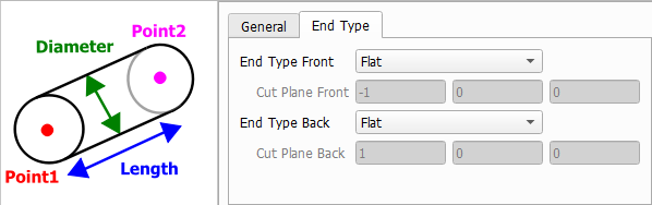
A Short fiber is a straight fiber with a finite length. A short fiber is defined by two points, given by the vectors after the keys Point1 and Point2, which specify the start and end points of the fiber.
Fiber End Type
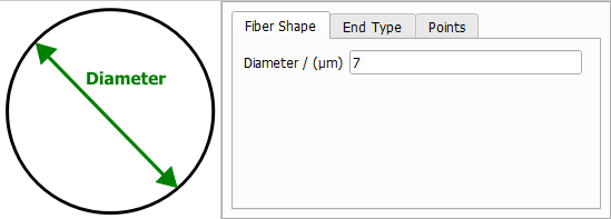
The circular fiber profile can be described by a single Diameter.
In general, the shape of the fiber endings is defined in the GAD format by the value after the keys FiberEndType1 (End Type Front) for the start point and FiberEndType2 (End Type Back) for the end point, which can have the following values:
- Flat: The fiber ending is planar, and the fiber direction is perpendicular to the according plane. No additional parameters are needed.
- CuttingPlane: The fiber ending is planar, and the according plane is perpendicular to a normal vector, specified by the vector after the keys CuttingPlane1 (Cut Plane Front) for the start point and CuttingPlane2 (Cut Plane Back) for the end point.
- Rounded: The fiber ending is rounded. No additional parameters are needed.
These options are available for all non-infinite fiber object types.
|
General Short Fiber
The definition of the GeneralShort fiber is similar to the Short fiber one. The fiber is defined by two points, given by the vectors after the keys Point1 and Point2.
The parameters of the fiber profile can change from the start to the end point. Hence, they have to be given for both points. For the circular fiber profile, this means that two diameters must be given, Diameter1 (diameter at Point1) and Diameter2 (diameter at Point2).
The fiber end types are defined as described above for the short fiber type.
|
Infinite Fiber
An Infinite fiber is a straight fiber with infinite length. The fiber is defined by one point, called Center in the user interface or Position in the GAD file, and one direction, given by the vector after the key Direction.
An infinite fiber cannot be created in a periodic domain.
The circular fiber profile is again described by a single Diameter. Naturally, infinite fibers do not have fiber end types.
|
Curved Fiber
A CurvedFiber is a non-straight finite fiber, composed of several linear segments. The linear segments form a polygonal line.
The circular fiber profile is again described by a single Diameter.
The fiber end types are defined as described above for the short fiber type.
The polygonal center line is described by a Number of Points and the positions of Point1, Point2, … in the table below.
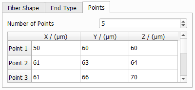
In the GAD file, the NumberOfSegments is given instead, which corresponds to the given Number of Points -1.
|
General Curved Fiber
The GeneralCurvedFiber is the most general fiber type supported by GeoDict. The fiber is composed of several linear segments, and the fiber profile can change over the length of the fiber.
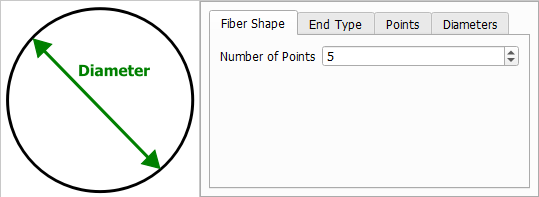
On the first tab, enter the Number of Points describing the polygonal center line.
The fiber end types are defined as described above for the short fiber type.
On the third tab, enter the coordinates of each point.
On the fourth tab, define the fiber profile for each segment, where the number of segments corresponds to the number of points minus one. For the circular fiber profile, this demands defining two diameters, one diameter at the start of a segment, and one at the end of a segment. It is not necessary that the diameter at the end of one segment matches to the diameter at the beginning of the next segment, but if they do, there will be a smooth transition of diameters along the fiber.
In the GAD file, the number of segments is given by the value after the key NumberOfSegments. The profile parameters are given in submaps: the parameters for the first segment are in Segment1, the parameters for the second are in Segment2, and so on.
The linear segments form a polygonal line. The coordinates of the points, which define the polygonal line, are given by the vectors after the keys Point1, Point2…, where NumberOfSegments+1 points are specified.
|