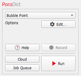
Bubble Point
The Bubble Point test is done to determine the Bubble point pressure. The Bubble point pressure is defined as the pressure at which the first bubble of gas appears while increasing pressure on a sample filled with a fluid. It must be sufficient to overcome the surface tension of the fluid and it is a direct measure of the effective pore diameter. Find more details about the theory behind the Bubble Point algorithm in the Theoretical Basics section.

|
Important! The structure resolution has to be high enough so that the smallest pore throat has at least a resolution of 5 voxels. Otherwise the detected bubble point may not be at the correct location.
|
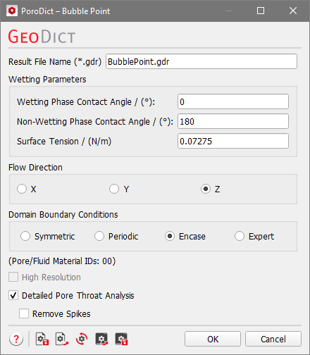
The Bubble Point dialog opens when clicking the Edit… button.
At the top of the dialog, enter the Result File Name. The result file is saved in the chosen project folder (File → Choose Project Folder in the menu bar).
 Wetting Parameters
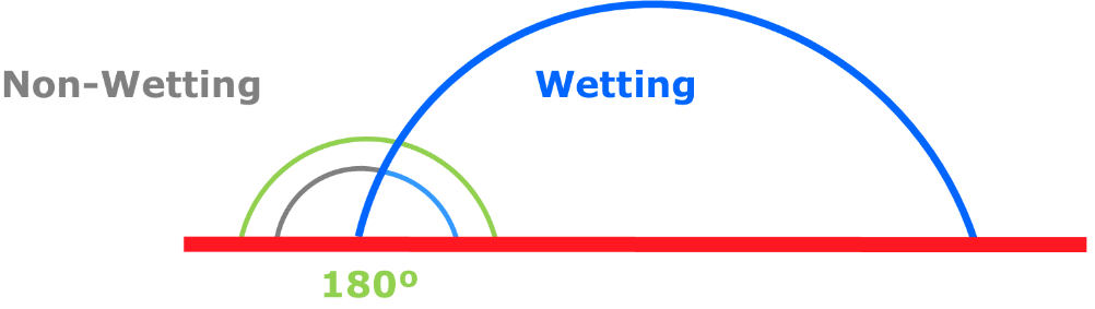
Choose the Wetting Phase Contact Angle and the Non-Wetting Phase Contact Angle.

|
Know how! The sum of the contact angles is 180º (shown in the picture are 70º and 110º) and when changing one of the two values the other is adjusted automatically.
|
Enter the Surface Tension of the fluid or use the default value corresponding to the surface tension of water.
|
Flow Direction
Choose the direction (X, Y, or Z) in which the pressure will be applied.
|
Domain Boundary Conditions
The Domain Boundary Condition in the chosen flow direction is always set to symmetric, for the tangential boundaries you are free to choose other boundary conditions.
The Domain Boundary Conditions can be chosen to be Symmetric, Periodic, Encase, or any combinations of those boundary conditions in all three directions with the choice of Expert.
Choosing the appropriate boundary condition depends on the structure’s design.
For example, imagine a structure with a cross-section as shown below.

For the three boundary condition options the resulting pore size is visualized in blue.
- If Symmetric boundary conditions are taken, the geometry is mirrored at the domain boundary.

- If instead the expected pattern of the geometry is repeated in all directions, Periodic boundary conditions should be selected. That has the effect that the objects and pores of the structure that end on one side of the structure reappear on the opposite side.

- If the structure should be encased with a closed wall, the Encase boundary conditions are used.

Check Expert to apply different boundary conditions for each direction. You can combine the three above mentioned boundary conditions independently for the directions. For example, the boundary conditions could be chosen to be Encase in X-direction, Symmetric in the Y-direction and Periodic in Z-direction.
|
High Resolution
To run the calculations in High Resolution might be useful when the path space is expected to be narrow. The standard algorithm computes distances directly on the voxel grid, i.e. when determining a pore size, only the distances from the center of a pore voxel to the center of a solid voxel are taken into account. High Resolution also takes the voxel surfaces and edges into account, so the computed distances correspond to the distance to the next surface or edge. The disadvantage of the High Resolution mode is that the calculation runtime and memory usage may increase by a factor of eight.
|
Detailed Pore Throat Analysis
Check Detailed Pore Throat Analysis to enable further geometric analysis of the smallest pore throat, including the location and the size. Multiple candidate throat planes along the percolation path will be tested by constructing planar ray-traced planes with varying tilt angles. The plane with the smallest area will be used for further analysis. This includes calculation of the hydraulic diameter, a detailed plot of the pore throat and enables loading the voxelized pore throat into GeoDict.
|
Remove Spikes
This option is only available if Detailed Pore Throat Analysis is checked.
The circumference of the smallest pore throat may exhibit spike-like extrusions, which have a strong influence on the geometrical analysis run. With the Remove Spikes option, those are removed before running the geometrical analysis. We advise to always have a look at the pore throat plot, to identify spikes in the pore circumference.
|

|
Note! Either High Resolution or Detailed Pore Throat Analysis can be chosen, not both at the same time.
|