Results
The result file (*.gdr) is opened in the Result Viewer after the computation is finished.
Report
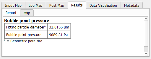
Always reported are the Fitting particle diameter, which is the diameter of the largest sphere that fits in the pore throat (computed with the Percolation Path command), and the Bubble point pressure. The bubble point pressure is computed from the determined through pore diameter (which is the fitting particle diameter) using the Young-Laplace equation:
where is the entered surface tension and is the entered wetting phase contact angle.
If a Detailed Pore Throat Analysis is run, additionally, the smallest pore throat is found and analyzed.
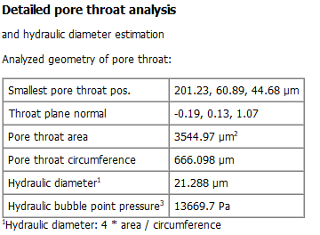
The position of the pore throat center point is given as Smallest pore throat pos. in metrical units. The normal vector of the pore throat plane (Throat plane normal) gives information about the orientation of the pore throat. The Pore throat area and the Pore throat circumference are used to calculate the Hydraulic diameter as:
The Hydraulic bubble point pressure uses the Young-Laplace equation with the hydraulic diameter for , which yields a more precise bubble point pressure.
Plots
Plots are only available if a Detailed Pore Throat Analysis was conducted.
For better understanding, we show the example structure where the found pore throat (viewed from below) is marked in blue. You can load this kind of visualization from the Data Visualization tab.
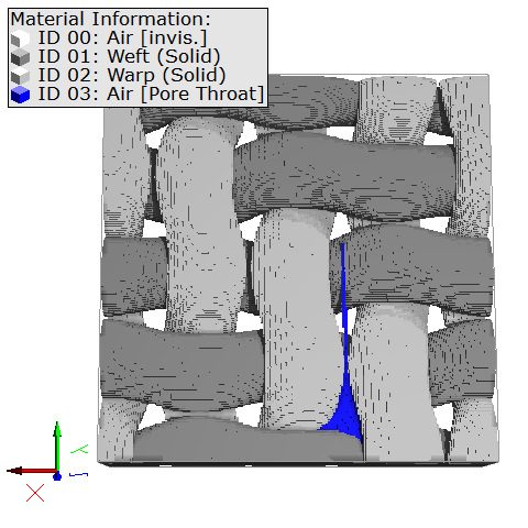
The only plot shown in the Plots tab is the pore throat area top view. The area surrounded by the blue Throat circumference line corresponds to the blue area in the example above and is the outline of the pore throat.
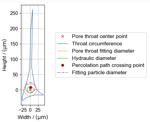
Up to five other types of data can be plotted:
- The Pore throat center point is the center of the pore throat calculated as center point of the pore throat fitting diameter circle.
- The Pore throat fitting diameter describes the maximal circle around the pore throat center point. This parameter considers only the two dimensions of the cross section. Thus, it is only used for visualization and not for the bubble point computation. The corresponding plot is disabled by default. It can be enabled by right-clicking in the plot and checking the corresponding box.
- The Hydraulic diameter is calculated as shown above and shown is the circle with the same diameter around the Pore throat center point. It can be quite different from the Fitting particle diameter, especially for pore throats with sharp angles.
- The Percolation path crossing point is the point, where the percolation path crosses the pore throat. As the percolation path considers all three dimensions, the percolation path crossing point and the pore throat center point can be different.
- The Fitting particle diameter is the diameter of the spherical particle fitted into the pore throat when computing the percolation path. The percolation path crossing point is the center point of the circle described by this parameter.
|
Know how! If the pore throat circumference has spikes like the one shown above, we recommend to enable the Remove Spikes option. |

Effects of Remove Spikes
When Remove Spikes is used, the spikes seen in the circumference are removed before analyzing the pore throat geometry.
Therefore, the results for the Detailed Pore throat Analysis in the Report tab and the pore throat area top view plot may vary. Below, observe that the spike causing a large height of the pore throat is removed when activating the Remove Spikes option. The results without this option are shown on the left and the results with this option are on the right.