Domain Size and Voxel Length
The domain size should be determined based on the original physical dimension of an STL file. First, set the Unit in File. The floating point values stored inside an STL file may denote different units. This information is not stored in the STL file itself, so it has to be set manually.
After the unit has been set, the extension of the CAD objects in X, Y, Z direction are shown in the Min Coordinate and Max Coordinate fields at the bottom of the dialog. In this example, the structures span a range from -100 mm to 190 mm in X-direction, from -100 mm to 100 mm in Y-direction, and from -110 mm to 508.3 mm in Z-direction.
Next, define the bounding box (domain size) of the voxel structure. It is possible to enter the values manually or to find a box that completely contains the structures to import automatically by clicking Suggest.
|
Important! You must set the correct Unit in File before using Suggest. |


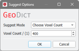
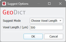
With Suggest, the domain size and shift values are automatically entered into the dialog in such a way that the complete surface mesh(es) is(are) inside of the domain.
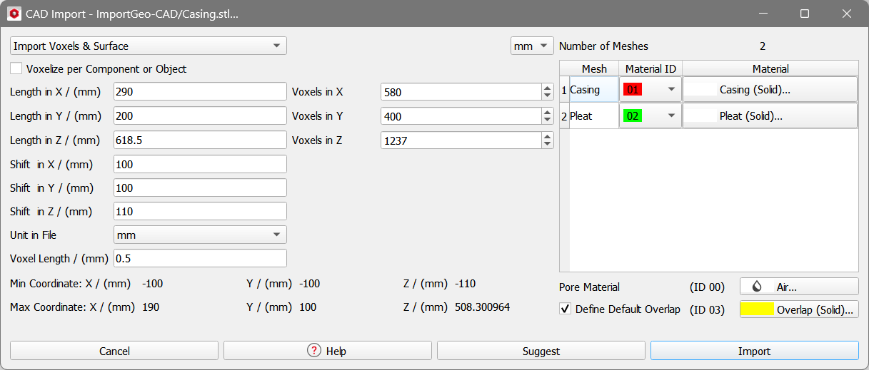
The domain size is defined by the parameters Length in X, Length in Y and Length in Z. The chosen Voxel Length defines the number of Voxels in X, Voxels in Y and Voxels in Z in each of the space directions.
The origin of the created domain is fixed at (0,0,0). To move the imported meshes inside of the domain, Shift in X, Shift in Y, and Shift in Z are added to the coordinate values when importing the surface meshes. In the above example, the min. coordinate value in X-direction lies at -0.1 m, which is shifted by 100 mm to end up at 0.0 at the exact boundary of the domain.