Options
After clicking the Edit… button, the Thickness Estimation dialog opens. At the top of the dialog, you can enter the Result File Name. The result file with the given name is saved in the chosen project folder (File → Choose Project Folder in the menu bar). The parameters are organized into the Fitting Options and Minimizer Options tabs.
Fitting Options

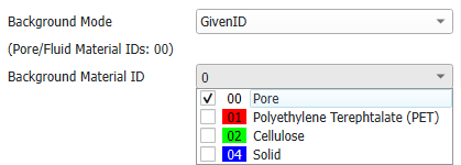
In the Background Mode pull-down menu, choose Pore to assign the Material ID corresponding to pore space (“background”) and exclude it from the calculations. The Material IDs that are recognized by GeoDict as background are given below as Pore/Fluid Material IDs. Alternatively, choose GivenID to assign one or multiple Material IDs to the pore space (only for the calculations within Thickness Estimation) and select the Material IDs from the Background Material ID pull-down menu.
In the Direction panel, one or more through directions for the thickness estimation can be chosen from the three principal directions X, Y, and Z.
In the Fit Selection panel, one or multiple fitting types (Fit 1 to Fit 6) can be selected. In the Result Viewer, the selection can be changed for post-processing calculations. This feature is particularly useful for comparing results across various fitting types. Additionally, to facilitate an easier selection, you can employ the Questionnaire, which automatically chooses fitting types based on the provided responses.
More precisely, a distinction is made between media with a homogeneous density distribution (Uniform) and media with a density gradient (Gradient). Furthermore, either the absence (Whole) or presence of an inlet area and outlet area is considered. In the latter case, these areas can be non-empty, allowing for solids such as fibers to stick out of the medium. The transition between inlet and medium (and medium and outlet) can be approximated either by a sharp transition zone (Sharp) or by a smooth transition zone, which results in a non-zero surface length (Smooth).
Fits 3 to 6 take an inlet/outlet area into consideration. If Write Inlet and Outlet to a .gdt file is checked, the structure of the detected inlet and outlet is written to a .gdt file in the project folder and can be loaded in the Data Visualization tab of the Result Viewer. Check Write Cropped Geometry to a .gdt file to save the structure without inlet and outlet as .gdt file. This file can also be loaded from the Data Visualization tab.
Fits 5 and 6 assume that the medium begins at the center of the inlet area and ends at the center of the outlet area. This definition is modified by adjusting the Thickness SVP Threshold value, the technical specifics of which can be found in the tooltip.
Minimizer Options
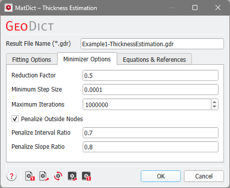
The minimization method includes several numerical parameters that can be fine-tuned under the Minimizer Options tab. Detailed information about these parameters is available in the tooltips and can also be found in the published document by Frank et al., 2024. These options are intended for experts; the default values are generally suitable for common porous media.
