|
Navigation: GeoDict 2026 - User Guide > Image Analysis > PoroDict > Open and Closed Porosity |
Scroll |
Options
At the top of the dialog, enter the Result File Name. The result file is saved in the chosen project folder (File → Choose Project Folder in the menu bar).

Control how many threads are used for the computation. Parallelization is possible if your license and hardware allow it. The Parallelization Options dialog opens when clicking the Edit button and you can choose between Sequential, Parallel (Shared Memory), or Automatic Maximum of Threads.  Selecting Sequential will not apply parallelization and only one thread is used for the computation. 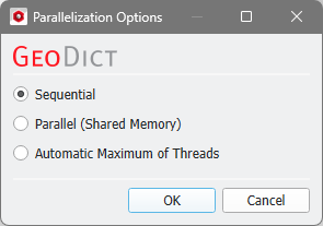 When Parallel (Shared Memory) is selected, the Number of Threads can be entered. Below, the Number of CPU Cores that the current machine has, the maximum number of Licensed Threads and the number of those licensed threads that are available (Available Threads) are shown in the dialog. Of course, the maximal number of parallel processes you can use, is the smallest of those three numbers. 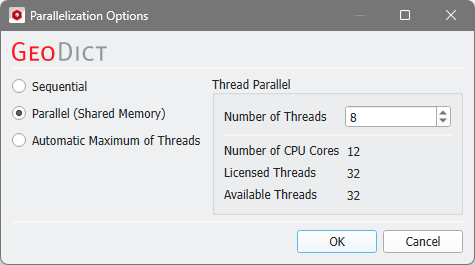 If Automatic Maximum of Threads is selected, the number of parallel processes is automatically selected for optimal speed, based on the CPU cores and licensed parallel processes. 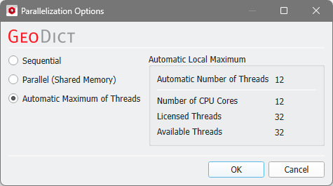 The Automatic Local Maximum of processes is automatically selected, which is the minimum of Number of CPU Cores, Licensed Threads, and Available Threads. |
Select one or more Inflow Planes to which the pores are open and considered as part of the open pore network. You can imagine that a fluid invades the structure from the inflow plane and all pores that are reached by the fluid are considered as open pores. For example, here with the default Z- (x-y-plane through z=1) and Z+ (x-y-plane through z=NZ) checked, the inflow planes are located at the top and at the bottom of the structure. Then, pores that are connected to the inflow planes are marked as open pores (white), and pores that do not open to the inflow planes are considered as closed pores (marked in green). |
When you select Periodicity, the boundary pores in that direction will be periodically connected to the opposite domain side. Directions which you choose as Inflow Plane cannot be selected for Periodicity. In the example below, Z- and Z+ were chosen as inflow planes. In the middle, the resulting open (white) and closed (green) pores when no Periodicity was chosen are shown. Only pores with a direct connection to the Inflow Plane are classified as open pores. On the right, Periodicity in X direction was selected. Now, the pore at the top left (touching X- boundary) is periodically connected to the X+ boundary to which the large pore has also a connection. Thus, the pore at the top left is also connected to the inflow planes and treated as open pore. |
With the Neighborhood Mode choose how the voxels from the pore space material in the structure are allowed to be connected to each other. The different Neighborhood Modes are explained using this example.  Two voxels can be connected through faces, edges, and vertices (corners). Voxels that share a face, do also share edges and corners, as you can observe for the red and the blue voxel. The blue and the green voxel share an edge and the corner points of this edge. Finally, the blue and the yellow voxel share only one vertex (corner point). Thus, checking Face is more restrictive than choosing Face or Edge, and this is more limiting than selecting Face, Edge, or Vertex. When choosing the Neighborhood Mode Face only the red and the blue voxel are connected. When choosing Face or Edge the red and the blue voxel and the blue and the green voxel are connected. Finally, if Face, Edge, or Vertex is chosen, the red and the blue voxel, the blue and the green voxel and the blue and the yellow voxel are connected. |
 Write Open and Closed Pores as *.gdt-File
Check Write Open and Closed Pores as *.gdt-File to save a structure file, where the closed pores get another Material ID than the open pores. The resulting structure files of the examples for the parameters Inflow plane and Periodicity are those *.gdt files. You can load this structure file into GeoDict from the Data Visualization tab in the Result Viewer.  If you choose to save open and closed pores as *.gdt file, you have the option to Mark Dead-End Pores in *.gdt-File. This saves a further classification (as different Material IDs) of the open pores into the file:
In the example below, Z- and Z+ were chosen as inflow planes and no periodicity is applied. When Mark Dead-End Pores in *.gdt-File was checked, the open pore at the top will be marked as dead-end pore, because it only has connection to the Z+ inflow plane. The large pore at the right goes from top to bottom and is connected to both inflow planes. Thus, it is marked as through pore. |

Write Voxel Geometry with Pore Indices (*.g32)
Check Write Voxel Geometry with Pore Indices (*.g32) to save an index image as *.g32 file, where each pore is assigned an individual index number. You can load this file into GeoDict from the Data Visualization tab in the Result Viewer. In the example below, Z- and Z+ were chosen as inflow planes. When no periodicity is checked, the pore at the top left is not connected to the large pore on the right, so they have different index numbers (resulting in different colors). If periodicity is applied in X-direction, the two pores are connected and have the same index number in the g32 file. |
©2026 created by Math2Market GmbH / Imprint / Privacy Policy
