The Hysteresis for Oil-Water Setups GeoApp predicts a capillary pressure hysteresis cycle in an oil-water setup with primary drainage, spontaneous and forced imbibition, and, if selected, secondary drainage.
Modules needed to run this GeoApp:
SatuDict
Click Edit to open the Hysteresis for Oil-Water Setups Parameters dialog.
Select a Result File Name fitting to the current project.
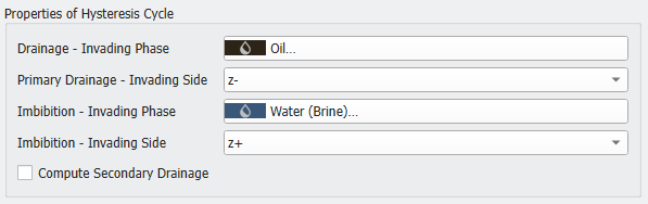
Select a material for the Drainage – Invading Phase and set the Primary Drainage – Invading Side. Choose an Imbibition - Invading Phase and set the Imbibition – Invading Side.
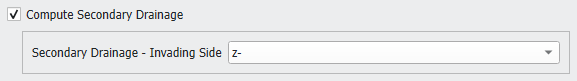
Select if also Secondary Drainage should be considered in the computation and choose the invading phase boundary for it.
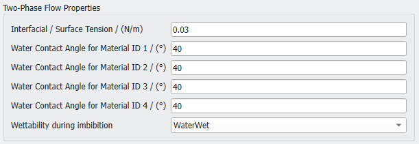
Define the Interfacial / Surface Tension in N/m between the two material phases, e.g., water and oil. At the beginning the structure is filled with water and all solids are water-wet. For up to four solid materials the Water Contact Angle can be set. During the primary drainage simulation oil enters the structure. The contact angle of the solids to the oil is , where is the Water Contact Angle.
After the primary drainage, the wettability of the solids may change for the imbibition and secondary drainage. The Wettability during imbibition can be selected from the pull-down menu.
If WaterWet is chosen, nothing changes after the primary drainage and all solid surfaces remain water-wet.
For MixedWet the wettability only changes locally after the primary drainage.
If OilWet is selected, the wettability changes globally after primary drainage. All solid surfaces that are covered by oil change from water-wet surfaces to oil-wet surfaces. They are then non-wetting against water.
In the case of a changing wettability, the new contact angles for the oil-rock contacts must be defined. Again, for up to four solid material IDs the Oil-Wet Contact Angles can be defined.
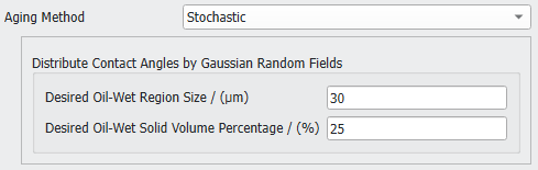
For a MixedWet set-up additionally the distribution of the oil-wet solids must be specified. First, select an Aging Method and then set the corresponding parameters. The aging method introduces which surfaces change their wettability after the primary drainage and before the imbibition.
For a Deterministic aging method, the wettability is changed at surfaces in large pores and in contact with the invading oil. The Pore volume considered for "aging" defines the limit for the material reassignments to oil-rock surfaces in large pores. A geometric pore size distribution is applied to determine the pore space that allows consideration of oil-wet surfaces with adjusted contact angles. For example, a value of 70% means that the largest 70% of the pores are changed from water-wet to oil-wet. A higher percentage leads to more contact material changes and an increased saturation change during forced imbibition, while the saturation changes during spontaneous imbibition are decreased.
A Stochastic aging method distributes the wettability changes using Gaussian random fields. Define the Desired Oil-Wet Region Size, representing the standard deviation for the applied Gaussian distribution. Additionally, enter the Desired Oil-Wet Solid Volume Percentage.
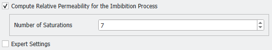
To compute the relative permeability during the imbibition check Compute Relative Permeability for the Imbibition Process. Define the Number of Saturations for which to compute the relative permeability. The default number of 7 means that for seven different saturations of the structure the permeability is computed. Increase the number to obtain more data points on the relative permeability curve.
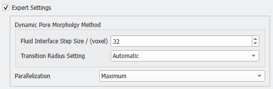
Finally, determine the Expert Settings. Here, define the Dynamic Pore Morphology Method parameters and the Parallelization.
The Fluid Interface Step Size defines how many voxels the computed fluid interface can move in each step. Lower values might increase the runtime significantly.
The imbibition starts with the spontaneous imbibition part. At some point, defined by the Transition Radius, the imbibition changes from spontaneous to forced:
For the Transition RadiusSettingAutomatic this point is determined automatically.
For a Manual Transition Radius, you define the sphere radius in voxel at which the dynamic transition from spontaneous to forced occurs. The meniscus of the water-front can be interpreted as a part of a circle. If this circle has a radius larger than the transition radius, the meniscus flips over, and the forced imbibition applies. This parameter is experimental. Examine the results carefully, especially if contact angles close to 90° are chosen.
For the Parallelization of the execution either use the Maximum number of cores or enter a Manual value.
Click OK to save the settings. Click Run to perform the hysteresis simulation.
Results
When the simulation is finished, the result file automatically opens in the Result Viewer.
The Results - Plots tab contains plots for Hysteresis, Relative Permeability, and Relative Permeability at irreducible Water (Brine) Saturation.
To obtain the Relative Permeability values, the permeabilities of the different saturation steps are divided by the absolute permeability.
For the Relative Permeability at irreducible Water (Brine) Saturation the effective permeability of the state with irreducible water saturation (at the end of the primary drainage) is used for normalization.
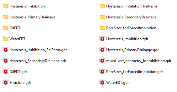
Several result files and result folders are generated and can be found in the project folder. The prefix is based on the chosen Result File Name (default is Hysteresis).

 Properties of Hysteresis Cycle