Hysteresis
The Hysteresis GeoApp performs a hysteresis simulation of the SatuDict functionalities Drainage and Imbibition (both with invading fluid connected to a reservoir and the displaced fluid can leave a residual) in succession. This GeoApp repetitively runs the Capillary Pressure command in the same way as it was explained in Capillary Pressure with Hysteresis Effect until the chosen Number of Cycles is reached.

|
Modules needed to run this GeoApp:
SatuDict
|
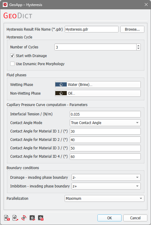
After clicking Edit…, enter the Hysteresis Result File Name and the necessary parameters.
 Hysteresis cycle
Enter the desired Number of Cycles, which means the number of SatuDict computations. The minimum value is 2, so that at least one drainage and one imbibition simulation will be performed. Check the box Start with Drainage? to first compute a drainage simulation, otherwise an imbibition will be simulated at the beginning. In the example shown above, 3 SatuDict simulations are done: first a drainage, followed by an imbibition, and finally a secondary drainage.
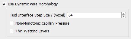
You can decide to Use Dynamic Pore Morphology, which has the same options as in the Capillary Pressure Curve command. Additionally, you can set the Fluid Interface Step Size as in the Solver Parameters tab of Capillary Pressure Curve.
|
Fluid phases
With Wetting Phase and Non-Wetting Phase select the fluids involved.
|
Important! If you start the computations with a Drainage simulation, the Wetting Phase must be present in the loaded structure. Similarly, if you decide to start with an Imbibition simulation, the Non-Wetting Phase has to be present at the beginning. The reason is, that in the simulations the corresponding fluid will be displaced.
|
|
Capillary Pressure Curve computation - Parameters
Set the Interfacial Tension, the Contact Angle Mode, and the Contact Angle with respect to the Wetting Phase for up to four solid material phases. The parameters are similar to those from Capillary Pressure Curve, except that the contact angle mode Constant Contact Angle is not available here.
|
Boundary conditions
Select the invading phase boundary for both Drainage and Imbibition. The other five domain boundary sides are set to Displaced Fluid Outlet (see also Boundary Conditions).
|
Parallelization
Choose to compute with Maximum parallelization or set a Manual number of threads.
|
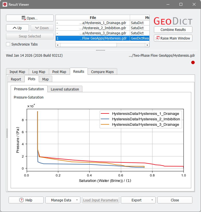
Results
After the Hysteresis computation has finished, the Result Viewer opens. The Header section box lists all the Imbibition and Drainage result files of each cycle. The hysteresis result file is an automatically combined result file showing the Pressure-Saturation curves in a single plot.