Saturation Experiment
The Saturation Experiment tab is divided into three groups: Experiment, Connectivity, and Use Dynamic Pore-Morphology Method. Depending on the choices made before, some options may not be editable.
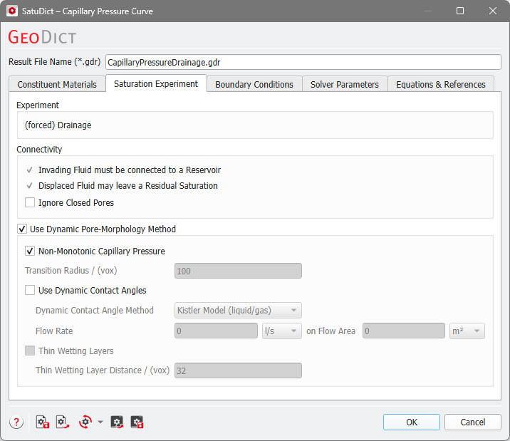
Experiment
Observe which kind of experiment is performed. This depends on the choice of the contact angles made in the Constituent Materials tab.
If all contact angles of the invading fluid are above 90° then a Drainage experiment will be performed, where the invading fluid is forced into the structure.
If all contact angles of the invading fluid are below 90° then an Imbibition experiment is performed, where the invading fluid enters the structure spontaneously.
In mixed-wet cases, where the contact angles of the invading fluid are above and below 90°, then spontaneous + forced Imbibition are computed.
Connectivity
The pore size and the pore connectivity to the Invading Fluid reservoir or Displaced Fluid reservoir determine the final distribution of the phases.
Check Invading Fluid must be connected to a Reservoir to enforce that the invading fluid is continuously connected to a phase reservoir at a given spatial location outside of the domain (defined in the Boundary Conditions tab). If this is unchecked, it models the sudden appearance of the wetting phase as condensation on the surface of the material in the structure. If a Drainage simulation is performed, Invading Fluid must be connected to a Reservoir cannot be unchecked.
The option Displaced Fluid may leave a Residual Saturation allows to leave a residual in pores that are separated from the displaced fluid reservoir, e.g., by the invading fluid. In this case, the displaced fluid needs to be connected to a reservoir, also defined in the Boundary Conditions tab. The residual of the displaced fluid is assigned a new Material ID. In general, it is recommended to enable this option.
|
Know how! Disabling this option is done for mercury intrusion capillary pressure experiments where mercury invades the pore space and displaces vacuum. Use the Mercury Porosimetry & Capillary Pressure command for simulating MICP experiments. |

Check Ignore Closed Pores to fill only the open pores with the invading fluid. Open pores are connected to the inflow and outflow region. All pores not connected to the domain boundary (closed pores) are pores without fluid at the beginning of the simulation. These closed pores are ignored and considered as solid regions during the simulation and in the post processing when computing saturations. After the simulation they are assigned to a separate material ID.
Dynamic Pore-Morphology Method
Check Use Dynamic Pore-Morphology Method to use this method for dynamic simulation of the drainage and imbibition processes.
|
Important! This option is required for mixed-wet cases! If you enter mixed-wet contact angles, the dynamic pore-morphology method is automatically activated. |

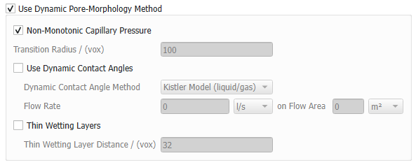
Select Non-Monotonic Capillary Pressure to allow the capillary pressure to drop down during a drainage simulation as the invading fluid passes through a pore-throat. During an imbibition simulation, the capillary pressure can rise again, when the invading fluid passes a big pore body.
The option to define a Transition Radius is only available for mixed-wet cases, where there is a transition from imbibition to drainage algorithm. With the Non-Monotonic Capillary Pressure option, it is possible to switch dynamically between the two algorithms several times (automatically done during calculations). In this case the Transition Radius determines at which interface curvature radius (in voxel) corresponding to the fluid-fluid interface the switch happens.
Check Use Dynamic Contact Angles allow for the entered contact angles to change dynamically. See Dynamic Contact Angles for more details. Below, choose the one of the Dynamic Contact Angle Models, Kistler (for liquid/gas systems) or Cox (for liquid/liquid systems), depending on the aggregate state of the fluids in the structure. For both models, the Flow Rate of the invading fluid on a Flow Area must be given. These settings can be based on the experimental conditions you are trying to recreate, i.e., based on the Flow Rate of an injection pump for the specific fluid and the Flow Area of the injection piston (commonly 1 – 1.5 inch²). This will ensure that the simulations are nearing the experimental setups the most.
To consider a modified connectivity check for thin wetting layers, check Thin Wetting Layers and define a Thin Wetting Layer Distance in voxels. When enabled, wetting residuals not more than the defined distance away from the invading wetting phase front are always treated as connected. In addition, new wetting residual layers may emerge in small pores near the invading wetting front. This option is only available for imbibition processes.