Solver Parameters
The Solver Parameters define the settings for the solver run and the output files.
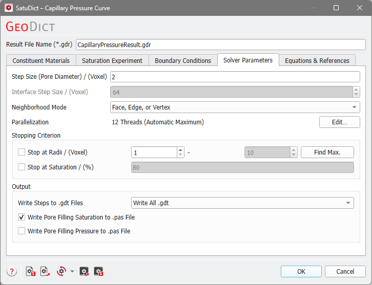
Step Size (Pore Diameter)
The pore diameter, together with the connectivity rule based on the Neighborhood Mode and the defined contact angles, determine the distribution of the invading fluid and displaced fluid phases.
The pore sizes to be considered for the calculations can be defined by entering the Step Size. The algorithm increases or decreases the sphere diameter (and thus changes the capillary pressure) from step to step by this amount. Small values increase the accuracy of the result but lead to longer calculation times.
Interface Step Size
This feature is only available if the Dynamic Pore Morphology Method is used. It specifies how far the interface between the phases is allowed to move within one simulation step and like this influences the accuracy of the simulated capillary pressure curve. The Dynamic Pore Morphology Method tries to approximate the specified interface distance, but in some cases smaller interface distances are realized. If the Interface Step Size is small, then the accuracy and thus the number of simulation steps is increased but it also increases the overall runtime.
Neighborhood Mode
The Neighborhood Mode determines how the voxels of the material occupying the pore space in the porous media are perceived as belonging to a connected group.
The different Neighborhood Modes are explained using this example.

Two voxels can be connected through faces, edges, and vertices (corners). Voxels that share a face, do also share edges and corners, as you can observe for the red and the blue voxel. The blue and the green voxel share an edge and the corner points of this edge. Finally, the blue and the yellow voxel share only one vertex (corner point).
Thus, checking Face is more restrictive than choosing Face or Edge, and this is more limiting than selecting Face, Edge, or Vertex.
When choosing the Neighborhood Mode Face only the red and the blue voxel are connected.
When choosing Face or Edge the red and the blue voxel and the blue and the green voxel are connected.
Finally, if Face, Edge, or Vertex is chosen, the red and the blue voxel, the blue and the green voxel and the blue and the yellow voxel are connected.
Parallelization
Control how many threads are used for the computation. Parallelization is possible if your license and hardware allow it.
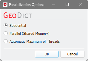
The Parallelization Options dialog opens when clicking the Edit button and you can choose between Sequential, Parallel (Shared Memory), or Automatic Maximum of Threads.

Selecting Sequential will not apply parallelization and only one thread is used for the computation.
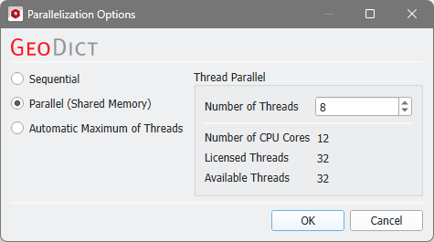
When Parallel (Shared Memory) is selected, the Number of Threads can be entered. Below, the Number of CPU Cores that the current machine has, the maximum number of Licensed Threads and the number of those licensed threads that are available (Available Threads) are shown in the dialog. Of course, the maximal number of parallel processes you can use, is the smallest of those three numbers.
If Automatic Maximum of Threads is selected, the number of parallel processes is automatically selected for optimal speed, based on the CPU cores and licensed parallel processes.
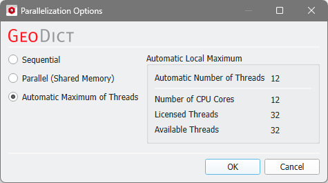
The Automatic Local Maximum of processes is automatically selected, which is the minimum of Number of CPU Cores, Licensed Threads, and Available Threads.
Stopping Criterion
If the check box Stop at Radii / (Voxel) is enabled, the simulation stops if either the minimal pore radius is reached (for a Drainage) or the maximal pore radius is reached (for an Imbibition).
Click Find Max to find the maximum pore radius present in the structure. The value found by Find Max is inserted automatically in the right box.
For a Drainage simulation, only the minimum radius can be set. If an Imbibition is computed, only the maximum radius can be set.
When Stop at Saturation / (%) is checked, the simulation stops if the invading fluid has reached this saturation value.
Output
Under the Output group it can be defined which information should be written as output files. If Write All .gdt is selected, the computed phase distributions are also saved as GDT files that can be imported for visualization.
The Material IDs and colors of the Invading Fluid, the Residual Invading Fluid, the Displaced Fluid, and the Residual Displaced Fluid are chosen automatically from the set of free Material IDs.
Depending on inlet and step size, different steps might lead to the same .gdt file. With Write Only Changed .gdt selected, only .gdt files that differ from previous ones are written to the hard drive. The result is a reduction in hard disk space consumption and a slight reduction in battery life.
Select Write No Files if no intermediate .gdt files should be saved.
If one of the options Write Pore Filling Saturation to .pas File and Write Pore Filling Pressure to .pas File is checked a .pas (pressure and saturation) file is written and saved in the result folder. This is a volume file and can be loaded from the result viewer in the Data Visualization tab. Depending on the checked options, either the saturation at which a voxel was filled, the pressure at which a voxel was filled, or both are written in the .pas file.