Rotation
The three-dimensional rotation of the image is defined in the Rotation panel. Enter values for the Phi, Theta, and Psi Euler rotation angles or an angle to simply turn about one axis.
This feature is particularly useful when the images are not aligned to the inherent axis of the structure and empty space is found around the images.
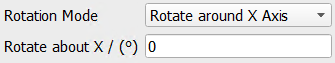
For the Rotation Mode select Euler Angles, Rotate around X, Y, or Z Axis.
The Euler rotation angles are applied following the order Phi → Theta → Psi.
For Rotate around X, Y, or Z Axis enter the angle for the rotation about X, Y, or Z.
Enlarge Image Automatically can be checked to avoid the cropping of the image after the rotation.
When you check Automatic Rotation, the entered parameters for the rotation angles are ignored and become inactive when clicking Apply. Instead, the Euler rotation angles are calculated automatically based on principal component analysis for the imported gray value image. From the pull-down menu for Automation Mode select Volume or Plane. For Volume the algorithm tries to align the structure to all three coordinate axes. For Plane only two major axes are aligned. Aligning only to two major axes can minimize unwanted rotations inside a planar structure.
To suggest a rotation, the current threshold settings are used. If Automatic Threshold is enabled, the Otsu method is used to threshold the image. Otherwise enter a Manual Threshold.
Values for the Euler rotation angles can also first be suggested by clicking Suggest - Volume or Suggest – Plane. Click one of these options to enter suggested values for Phi, Theta, and Psi.
Click Apply to rotate the structure with the current settings.
For example, here, a structure model is obtained first without rotation.
Then, to obtain a structure that has been rotated only about the Y-axis by 90° or by 180°, the following Euler Angles are used:
- 90° around Z-axis (fixed) + 180° around new X-axis (fixed) + -90° around new Z-axis (fixed)
- 90° around Z-axis (fixed) + 90° around new X-axis (fixed) + -90° around new Z-axis (fixed)
Of course, these two rotations can be obtained much easier, when selecting Rotate around Y-Axis for Rotation Mode, but the example helps to understand the Euler Angles. As they can rotate the 3D image in each desired direction, they are more powerful if the image should not only be rotated about one axis.
If you select Rotate as the Overlay, the resulting rotation is visualized in the 2D Slice Visualization area. The diagonal red, green, and blue lines show the resulting center line. In the following example, the image is rotated about the X-axis. Therefore, in the YZ-plane a blue and a green diagonal can be observed. After rotating, these are the new center lines.