|
Navigation: GeoDict 2026 - User Guide > Simulation & Prediction > BatteryDict > Battery > Charge Battery > Options |
Scroll |
Experiment
All parameters defining the charging simulation of the battery are defined on this tab.

From the pull-down menu Experiment Type, select the appropriate entry to simulate the charging or discharging of the battery cell or set a charging profile. Here, a charging simulation is chosen. For the experiment types Charge Battery Cell and Discharge Battery Cell select the Boundary Conditions in Through Direction and the Start and End Condition. How to Set a Charging Profile is explained here. |
 Boundary Conditions in Through Direction
The Boundary Conditions in Through Direction can be specified by a Charge Rate, a Current Density, by defining the Current, by defining the Cell Potential, or the Power Density.
|





The Start and End Condition for the charging simulation can be defined in several ways:
Depending on the selected boundary conditions, it is possible to set additional an end conditions to the simulation.
|









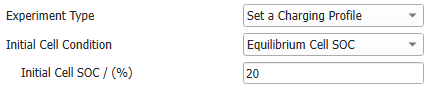
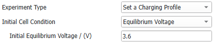
Charging Profiles are a series of charging, discharging, and relaxation simulations that are performed sequentially for the same structure. 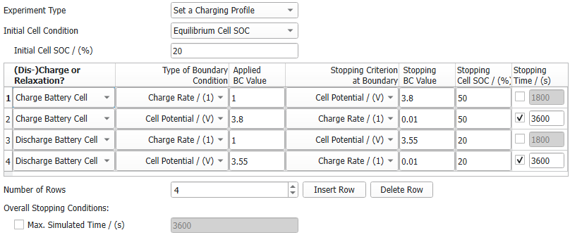 If Set a Charging Profile is selected as Experiment Type, the starting point for the first simulation can be defined
The starting point for the following simulations, defined in the charging profile table, is always the final state of the previous one. To define a charging profile, choose as many rows for the table as simulation steps desired by entering the Number of Rows. Select for each step, if the battery is charged, discharged, or if relaxation is simulated. For charging or discharging, define the Type of Boundary Condition (BC) and the corresponding Applied BC Value, in the same way as for simple charging simulations. The same options for the boundary condition (Charge Rate, Current Density, Current, Cell Potential, and Power Density) are available. For charging or discharging, next, the first stopping criterion for the selected boundary condition (Stopping Criterion at Boundary) is chosen for each simulation step. The available options depend on the Type of Boundary Condition.
Enter the Stopping BC Value for the first stopping criterion, for the second stopping criterion a stopping state-of-charge for the whole cell (Stopping Cell SOC / %) and for the (optional) third stopping criterion a Stopping Time. The computation ends for each simulation step, if the first one of the stopping criteria is reached. The next simulation step will continue from this state. For relaxation, no boundary conditions need to be defined, only the stopping time as the only possible stopping criterion of the relaxation step. In a relaxation step, the return of the battery cell to an equilibrium state after charging or discharging is simulated. The solver settings, including the time step, are set by BatteryDict to optimize the simulation time required for the relaxation step.  |

Boundary Conditions in Tangential Directions
Periodic or Symmetric boundary conditions can be selected for the Boundary Conditions in Tangential Directions. For periodic boundary conditions, the structure is assumed to repeat periodically in Y- and Z-direction and for symmetric boundary conditions, the structure is mirrored in Y- and Z-direction and the Li+ ions and electrons are reflected at the boundary in Y- and Z-direction. The connected and unconnected parts of the active materials and electrolyte depend on the boundary conditions, so they are determined when the simulation begins. |
©2026 created by Math2Market GmbH / Imprint / Privacy Policy
