Fiber Tab
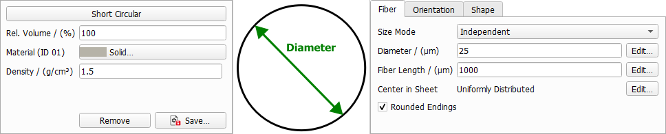
Define the general fiber parameters such as diameter, fiber length and center in sheet.
The different fiber types have different options. For example, the infinite fiber types don't have a parameter to define their length, since they are infinite.
Size Mode
All fiber types except for Infinite Circular have the parameter Size Mode. From the pull-down menu, three options can be selected. Here you can decide if the different diameter and length parameters of one fiber type should be interdependent.
 Independent
All diameter and length parameters are independent from each other, and thus have their own values and distributions available through their Edit... buttons.
|
Coupled
The different diameter/length parameters are coupled. Clicking the Edit... button for these parameters, .
The following structure, entirely made of short circular fibers, is generated with the coupled values for diameter and length entered in the coupled distribution table shown here. Observe the three distinct diameter-length combinations of short circular fibers:
- 50% with diameter 5 µm and length 80 µm,
- 20% with diameter 20 µm and length 120 µm, and
- 30% with diameter 10 µm and length 140 µm.
|
Aspect Ratio
The different diameter/length parameters are given with an aspect ratio. They depend on the first Diameter. The resulting diameter/length value then is the aspect ratio multiplied with the first parameter value, for example:
where Aspect Ratio is short for Diameter 1 - Length Aspect Ratio.
This way, you can, for example, generate fibers with a diameter distribution keeping the same aspect ratio to their length as shown below.
|
Diameter
Circular Fiber
A circular fiber has only one diameter value. The Diameter value can be edited by clicking the Edit... button to open the Diameter dialog box. The circular fiber diameter can be set to have a Constant value, or to follow a distribution (Uniformly in interval, Gaussian, Probability Distribution, or Log-Normal).
|
Elliptical and Cellulose Fiber
For non-circular fibers, such as elliptical and cellulose fibers, two diameter values (Diameter 1 and Diameter 2) need to be entered. Both diameter values are editable by clicking on the Edit... button and choosing the desired settings in the Diameter dialog boxes. They can be set to have a Constant value, or to follow a distribution (Uniformly in interval, Gaussian, Probability Distribution, or Log-Normal).
|
Wall Thickness
Cellulose Fiber
For cellulose fibers, the Wall Thickness must also be defined. The wall thickness is editable by clicking on the Edit... button and choosing the desired settings in the Wall Thickness dialog box. It can be set to have a Constant value, or to follow a distribution (Uniformly in interval, Gaussian, Probability Distribution, or Log-Normal).
|
Length
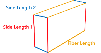
Fibers can have Finite (Short Fibers) or Infinite length. For short fibers the length must be defined. Additionally, for fibers with rectangular cross-section the parameters Length 1 and Length 1 - 2 Aspect Ratio define the side lengths of the cross section.
Fiber Length
Fibers can be Short or have Infinite length. The length of short fibers is editable by clicking on the Edit... button and choosing the desired settings in the Fiber Length dialog box. It can be set to have a Constant value, or to follow a distribution (Uniformly in interval, Gaussian, Probability Distribution, or Log-Normal).
|
Side Length
The the Side Length 1 and Side Length 2 for Rectangular fibers is editable by clicking on the Edit... button and choosing the desired settings in the Side Length dialog boxes. It can be set to take a Constant value, or to follow a distribution (Uniformly in interval, Gaussian, Probability Distribution, or Log-Normal).
Note, that the side lengths can also be oriented differently in the domain. This is because fibers can have different orientations in the domain which can be defined from the Orientation tab. For a fiber oriented in Y-direction with a rotation angle of 90° the Side Length 1 is parallel to the Z-axis and the Side Length 2 parallel to the X-axis. With an orientation angle of 0, the Side Length 1 will be in X-direction and the Side Length 2 will be in Z-direction.
|
Center in Sheet
The position of the fiber centers in Z-direction can be set to be Uniformly distributed in the sheet of paper or to follow a user-defined Density Distribution. This option is available for all fiber types. The values for Center in Sheet define the relative position in Z-direction of the fibers in relation to the given Sheet Thickness (which can be defined in the Create Options tab).
Density Distribution
In the following example, a paper with two types of fibers is generated. The gray fibers are Short Cellulose fibers with centers following a user-defined density distribution. The yellow fibers are Short Circular fibers with centers uniformly distributed in the paper sheet.
In the density distribution table, the left column values from 0 to 1 correspond to locations in the structure. In the Z-direction, the value 0 is the bottom and the value 1 is the top of the sheet.
The right column assigns relative density values at these locations. The value 3 at Z = 0.3 means that the probability for a fiber center to be located at Z = 0.3 is three times higher than at Z = 0.7, where the density value is 1. The fiber density increases and decreases linearly between the given locations in the Z-direction. Therefore, in the following example, the positions where a sharp transition is desired are given twice: once with positive density and once with density of 0.
Observe how, with the values in this table, the gray fibers occupy the area in the middle of the paper sheet (Z=0.3 to Z=0.7), whereas the yellow fibers’ centers are distributed uniformly in it.
|
Rounded Endings
Short fibers with any cross-section (Circular, Cellulose, Elliptic, or Rectangular) can be created with or without rounded ends by checking or leaving un-checked the Rounded Endings box. Observe the variation in the shape of the short rectangular fibers after checking the Rounded Endings box.