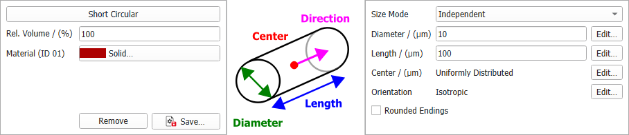
Define the general fiber parameters such as diameter, fiber length, and center distribution.
The different fiber types have different options. For example, the infinite fiber types don't have a parameter to define their length, since they are infinite.
The parameters that define the fiber's position and orientation in the structure are explained in sub-topics:
Orientation
Define if the fibers should have an isotropic or anisotropic orientation.
Center
Define how the fiber centers should be distributed throughout the domain.
Size Mode
All non-infinite fiber types have the parameter Size Mode. From the pull-down menu three options can be selected. Here you can decide if the different diameter and length parameters of one fiber type should be interdependent.
All diameter and length parameters are independent from each other and thus have their own values and distributions available through their Edit... buttons.
The different diameter/length parameters are coupled. Clicking the Edit... button for these parameters, the coupling can be defined in the distribution table.
The following structure, entirely made of short circular fibers, is generated with the coupled values for diameter and length entered in the coupled distribution table shown here. Observe the three distinct diameter-length combinations of short circular fibers:
The different diameter/length parameters are given with an aspect ratio. They depend on the first diameter (given by Diameter, Diameter 1, Side Length 1, or Dtex). The resulting diameter/length value then is the aspect ratio multiplied with the first parameter value, for example:
(4)
where Aspect Ratio is short for Diameter 1 - Length Aspect Ratio.
This way you can, for example, generate fibers with a diameter distribution keeping the same aspect ratio to their length as shown below.
A circular fiber has only one diameter value. The Diameter (or Dtex) value can be edited by clicking the Edit... button to open the Diameter (or Dtex) dialog. The circular fiber diameter can be set to have a Constant value, or to follow a diameter distribution (Uniformly in interval, Gaussian, Probability Distribution, or Log-Normal). Whether the parameter is given as Dtex or Diameter depends on the choice for Fiber thickness given by.
For a hollow fiber, the Inner Diameter Fraction defines which fraction of the entered (outer) diameter value is the inner diameter value. If the fiber thickness is given by Dtex, the inner and outer diameter are chosen to match the given fraction and Dtex values.
For Elliptical fibers, defined by two diameters, the Aspect Ratio is the relationship between the longer diameter (Diameter 1) and the shorter diameter (Diameter 2). If the fiber thickness is given by Dtex, the diameter 1 and 2 are chosen to match the given aspect ratio and Dtex values.
(6)
Length
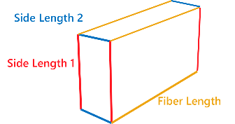
Fibers can have Finite (Short Fibers) or Infinite length. For short fibers the length must be defined. Additionally, for fibers with rectangular cross-section the parameters Length 1 and Length 1 - 2 Aspect Ratio define the side lengths of the cross section.
The length of Short and Curved fibers is editable by clicking on the Edit... button and choosing the desired settings in the Length (µm) dialog. The fiber Length and Side Length can be set to take a Constant value, or to follow a distribution (Uniformly in interval, Gaussian, Probability Distribution, or Log-Normal).
For fibers with rectangular cross-section, the Side Length 1 and the Aspect Ratio defining Side Length 2 can be entered. If the fiber thickness is given by Dtex, the Side Length 1 and 2 are chosen to match the given aspect ratio and Dtex values.
Short fibers with any cross-section (Circular, Hollow, Rosetta, Cellulose, Elliptic, Rectangular, and Angular) can be created with or without rounded ends by checking or leaving un-checked the Rounded Endings box.
Observe the variation in the shape of the short rectangular fibers after checking the Rounded Endings box.
For fibers with Rosetta cross-section, the Amplitude Fraction determines the length of the rosetta leaves, whereas the Number of Leaves defines how many leaves the rosetta has. The minimum number of leaves is three and the maximum is 20.
In polar coordinates, the cross-sectional shape is defined through
(8) Rosetta Cross-Section
where in is the angle in the cross-sectional plane and the Diameter value is the average of the minimal and maximal diameter. Thus, the amplitude is given through:
For Angular cross sections, the Number of Edges defines the number of edges in the cross-section. For three edges, for example, a triangular cross-section is obtained. The minimum number of edges is three and the maximum is 20.
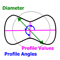
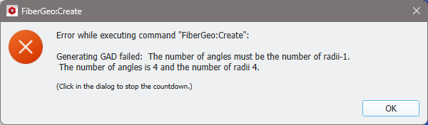
Complex cross-sections are obtained by varying the Profile Angles and the Profile Values. The Profile Values and the radius (r = Diameter/2)are multiplied to obtain the local radius for the corresponding Profile Angle. The first profile value always corresponds to a profile angle of 0°. Thus, always enter one more profile value than profile angles.
If the entered number of angles is not number of values -1, an error message appears when clicking Generate.
For example, with a diameter of 10 µm, the following arbitrary cross-sections can be obtained by applying the indicated profile angles and profile values: