Labeling is the process of annotating images datasets so that an AI model can identify and separate different materials in your geometry. Labeling is necessary because segmentation models rely on accurately labeled training data to learn how to detect boundaries and shapes.
For all models, select the Number of Materials to be labeled in the image dataset. If you know how many materials are present in your sample, enter that number here. Otherwise, observe the different gray levels in your images and select the appropriate number.
Use the Material Database to select different materials. Click on the button next to the material you want to use, e.g., Pore. The checkbox to the right of each each material determines which material will be used to paint the labels.
In Navigation Mode , you can pan the image in the 2D Slice Visualization section with the left mouse button and zoom in and out with the right mouse button.
Select Painting Mode to start painting in the 2D Slice Visualization area. Make sure that Visibility is turned on and that AI-Labels is selected for Overlay. Painting Mode allows you to add labels to the scan using the left mouse button. Use the right mouse button to erase labels. Switch between materials by selecting the corresponding checkboxes. When you press and hold Shift, navigating in the 2D Slice Visualization section works the same way as in Navigation Mode.
If a label was not painted correctly, switch to Erasing Mode and erase the label by clicking and holding the left mouse button while moving the mouse over the label. Press and hold Shift to navigate the 2D Slice Visualization section in the same way as in Navigation Mode. Alternatively, you can erase labels in Painting Mode by pressing the right mouse button.
Use the Undo and Redo buttons to remove or restore previous label paint strokes. This allows you to easily remove labels that were painted in error or restore previous labels.
The default Circle Brush allows you to label a circular area around your mouse pointer with the currently selected material. Hold down the left mouse button to paint continuous strokes. Adjust the Brush Size to fit the size of the area being labeled. Reduce the size to capture fine components and increase it to quickly label larger sections of materials.
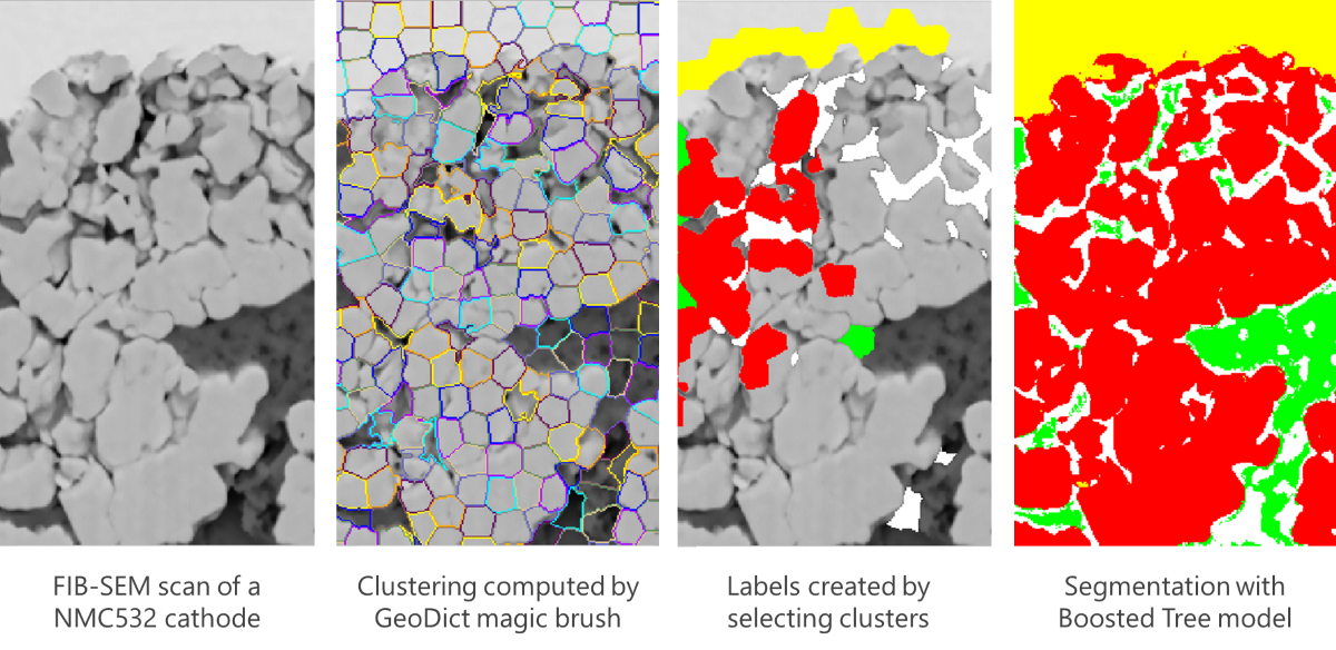
When you enable the Magic Brush, the images are analyzed and clustered based on edge recognition. These clusters are computed using the SLIC (Simple Linear Iterative Clustering) algorithm, which generates clusters based on gray value similarity and proximity in the image plane. Then, you can create labels by left-clicking on these clusters in Painting Mode. To show the clusters, enable Show Magic Brush Outlines. You can adjust the size of the clusters by changing the Brush Size. This mode makes labeling much easier for many image datasets.
Use the Lasso mode to label areas by tracing their outlines with your mouse. First, select this brush mode. Then, select the material that you want to label. Finally, change to Painting Mode. Your mouse pointer will indicate that you are labeling a single voxel. Click and hold the left mouse button, then trace the outline of an area (e.g., a single grain, fiber, or pore). A line connecting the start point of the label tracing and the current position of your mouse is always displayed in the overlay. Once you release the left mouse button, the area contained by your painted outline will be filled automatically. This allows you to precisely trace boundaries between different materials, where high precision is required, while automatically filling larger areas, which would otherwise be tedious to label manually.
Save the painted labels as a *.gld file by clicking Save Labels. We recommend saving labels regularly to avoid losing any progress, since labeling can take a lot of time depending on the complexity of the image dataset.
Click Load Labels to reload the training data whenever needed. Note that the label data must have the same dimensions as the currently loaded image.
The AI-LabelsOverlay will automatically activates when you select the AI segmentation. This overlay shows the current labels and allows you to add more labels when in Painting Mode.
If a trained model is loaded, you can also set the Overlay to Preview to view the segmentation results for the current slices.
When you change the Overlay to Mixed, you can view both the current Labels and the Preview of the current trained AI model. The labels are shown with less transparency than the preview. If the preview shows that the model needs more training, the Mixed view helps you concentrate further labeling on areas where the model did not classify the voxels correctly.
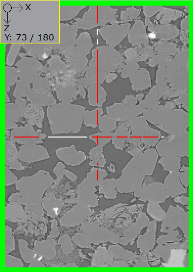
By using the different view directions, you can observe the labels on the slices that were labeled in the other two directions. In the example below, the center slices in the X- and Z-directions are labeled. Thus, when viewed in the Y-direction, two thin lines with white (material 1) and red (material 2) sections are labeled. If labels are erased on these lines, thin lines are erased in the respective slices in the other directions.
It is crucial to label the boundaries between different materials so that the model can learn to differentiate between them. If there are more than two materials, it is crucial to label all possible boundary combinations. While labeling boundaries is important, only label as close to the boundary as necessary to ensure that you are labeling the correct boundary. Otherwise, incorrect training data will be generated.
It is not necessary to label an entire slice. Be sure to label sections of each material, as well as the boundaries. Also, label entire structures, such as grains or fibers, so that the AI model can recognize the shapes present in your structure. You can also label multiple materials with different gray values as one (e.g., small pores contained in grains). The Unet models are powerful and can learn to combine these gray values into one material based on the shapes and geometries.
Clustering labels close together produces better results. For each labeled area, paint as many labels as possible to fully fill the output window.
Paint slices in all three directions, especially if the gray values differ significantly.
For the Unet3D method, be sure to label consecutive slices from the same area. This allows the model to learn 3D shapes within your structure.