For randomly curved and sine fibers, the Segment Length determines the length of the linear parts that build the fiber (finer segments), so that small values lead to well resolved fibers with smooth curving.
A smaller segment length leads to longer computation times when using Lay-Down Fibers. A large segment length leads to fibers with long straight segments.
In the following examples, all parameters for the short circular, randomly curved fibers with a length of 1000 µm are are left unchanged, while the Segment Length varies as indicated.
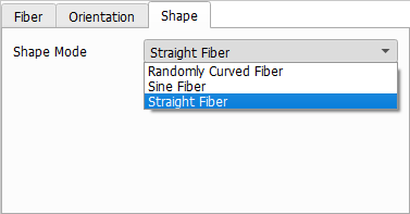
Straight Fiber
A Straight Fiber is straight by definition, so no additional shape parameters are available. To create straight fibers with Torsion, for example choose Randomly Curved Fibers with zero Randomness in Plane and zero Randomness Perpendicular as explained in the following.
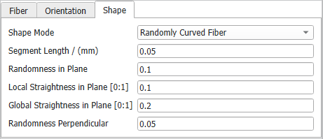
Randomly Curved Fiber
Randomly Curved Fibers follow a random curve determined by Randomness in Plane, Local Straightness in Plane, Global Straightness in Plane, and Randomness Perpendicular.
The values of these parameters describe how strongly a fiber may change direction from one segment to the next. The different parameters complement each other, whereby the straightness parameters control the amount of curvature locally or globally and the randomness parameters define the amount of random influences. For a more detailed explanation how the parameters influence the curvature, refer to the FiberGeo chapter.
The following examples show the effect of these parameters for short elliptical or circular Randomly Curved Fibers. The segment length is set to 20 µm for both types of fibers.
Initially, the Randomness in Plane is set to 0, as are all other three randomness parameters. Then, the Randomness in Plane is set to 0.1 and finally to 0.2. Too large values of Randomness in Plane lead to unrealistic results in this constellation. Observe that using Randomness in Plane, the deformation occurs only in the XY-plane and not in the Z-direction.
To achieve a deformation in the Z-direction, Randomness Perpendicular must be used. A structure created with a higher Randomness Perpendicular value (0.2) is viewed in 3D Rendering and in 2D Cross-section to show that the deformation occurs in the Z-direction while no deformation can be observed in the XY-plane.
The Local Straightness in Plane parameter controls how strongly fibers might change direction from one segment to the next. The values must be chosen between 0 and 1. Observe the effect of increasing the Local Straightness in Plane from 0 over 0.5 to 1, while the Randomness in Plane is kept at a constant value of 0.2. The segment length is 20 µm. The fibers appear locally straighter but are globally curved.
The Global Straightness in Plane parameter controls how strongly the fibers follow their main fiber direction. The values must be chosen between 0 and 1. Observe the effect of increasing values of Global Straightness in Plane (0, 0.1, and 1), while the Randomness in Plane is kept at a constant value of 0.1. The segment length is 20 µm. The fibers appear globally straighter, while they are still locally curved.
Sine Fiber
Sine (or sinusoidal curved) Fibers are following a sinusoidal curve where the length and amplitude parameters can be defined in two perpendicular directions.
The direction of the parameters Sine Length Lateral, Sine Length Vertical, Sine Amplitude Lateral, and Sine Amplitude Vertical is depending on the fiber orientation. For elliptical fibers, lateral and vertical describe the directions of the main axes.
The following examples show the influence of these parameters on sinefibers. The Segment Length is set to 25 µm (¼ of the sine length).
Setting higher values of Sine Length Lateral and Sine Length Vertical produces less sharply bent sine fibers. In the example the segment Length is kept at 25 µm and the lateral sine amplitude is kept at 0 to only apply vertical sine curvature.
The sine length can be set to have a Constant value, or to follow a diameter distribution (Uniformly in interval, Gaussian, or Probability Distribution).
Initially, Sine Amplitude Lateral and Sine Amplitude Vertical are set to 0 (as are the Rotation Angle and the Torsion Angle) to produce fibers that are straight. To better observe this effect, the Anisotropy in Plane has been set to 20.
Sine fibers have only a vertical component when the Sine Amplitude Vertical takes a value greater than zero, while the Sine Amplitude Lateral is 0 µm. Vice versa, they have only a lateral component when the Sine Amplitude Vertical is 0 µm and the Sine Amplitude Lateral is larger than zero. Setting both amplitude values larger than zero, the fibers have both, a lateral and a vertical component.
The sine amplitude can be set to have a Constant value, or to follow a diameter distribution (Uniformly in interval, Gaussian, or Probability Distribution).
Observe the effect of the combination of sine parameters with a Rotation Angle that follows a uniform distribution in the interval 0° to 90º. The fibers appear not only curved but also rotated.