|
Navigation: GeoDict 2026 - User Guide > Material Modeling > WeaveGeo > Complex Multi-Layer Weave |
Scroll |
Binding
The Binding tab shows the binding matrix and a 2D preview of the weave. The 2D preview of the Weft-Layer System is located at the bottom left of the window, the Warp-Layer System at the top right. The Binding Matrix is located at the bottom right.

If two warp threads overlap, they are marked with a yellow attention sign (triangle) with exclamation mark in the preview of the Warp-Layer System. The overlap is not checked in Z-direction. This initial overlap can be resolved by either adjusting the binding or using Shifts.
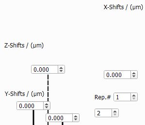 X- and Y-Shifts are shown in the previews while Z-Shifts are not. Please note that in case of Shifts in X- and Y-Direction, all threads belonging to the same layer will be shifted. In case of the Z-Direction, the distance between two layers is increased or decreased. For a Z-Shift of 0, the threads of the layers touch. That does not necessarily correspond to the position in Z-direction at which they are currently displayed in the preview. Since the structure generation is performed with an iterative physics-based simulation, the distances between threads might change during the generation. The properties of the threads can be defined for each thread individually or they can be repeated after a certain number of threads. This number is defined under Rep.# (Repetition). The number below Rep.# corresponds to the repetition of the weft threads and the number on the right corresponds to the repetitions of the warp threads. If the Rep.# is smaller than the number of threads in the corresponding system (weft or warp), the material color for the repeated threads is grayed out. This is shown in the example below where Rep.#=1 for the warp system. If the repetition number is set to the number of threads, individual thread types can be assigned for each thread. (See below where Rep.#=3 is set). To assign a thread type to a thread, open the Property Menu and select a thread type from the drop-down menu under Material. The available thread types are defined under the Materials and Thread Types tab. |
The preview of the Weft-Layer System shows all weft layers in vertical direction. The first layer is in the first column from the right. Each layer is displayed in a 2D preview and a table, where each cell represents one thread. The weft threads are represented by colored circles, the warp threads as lines. The color of both corresponds to the color of the cells in the table and to the color of the threads in the structure and stands for the Material of the thread. In the Visibility Settings, the different Materials can be activated/deactivated by clicking on the corresponding color. All threads with a deactivated material are invisible in the preview but will be generated, unlike hidden threads. This functionality gives you a better overview during the generation of complex weaves. The number in each cell represents the Shot Index. You can change the Shot Order using the drop-down menu. This assigns a shot index to each thread according to the selected pattern. If X is selected in the menu, the shot index can be assigned manually for each thread. This can be done in the Property Menu of the thread, which is accessed by clicking on the corresponding cell in the table.
Several other properties can be defined in the Property Menu. The Material can be changed and the thread can be hidden. Selecting Hide means that the thread will not be included in the weave after generation. Changing the Relative Shift moves the thread in the Y direction. This value is added to the Y-Shift value of the corresponding layer, as explained under Shifts. |

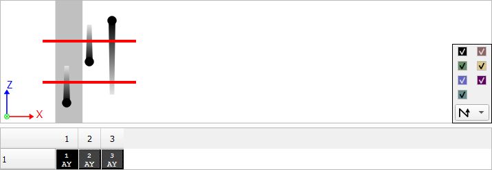 The preview of the Warp-Layer System shows all weft layers in horizontal direction, the first layer is in the first row from the bottom. The warp threads are represented by colored circles, and their trails indicate whether they come from the top or bottom. The weft threads are represented as lines. This represents the weaving process: The weft threads are present at first in the weaving machine and are therefore straight in the beginning. The warp threads are woven around the weft threads. The color of both corresponds to the color of the cells in the table and stands for the Material of the thread. All other elements of the Warp-Layer System are identical to the Weft-Layer System. |
The Binding Matrix panel has a column for each warp thread. The number of rows is defined by the maximum yarn count of all weft layers. 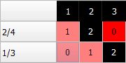 The numbers and colors in the first row show the Shot Index and Material color of the warp threads. The first column only shows the Shot Index of the weft threads. Each cell stands for the intersection of a warp and a weft thread. The numbers in the cells determine the position of the warp thread in Z-direction relative to the weft thread layers at that location. A value of 0 indicates that the warp thread is at the bottom of the weave, beneath the first layer of weft threads. Setting the maximum value, which is equal to the number of weft layers, means that the warp thread will lie on top of the weave. The color of each cell in the binding matrix corresponds to the color of the topmost thread. The color pattern of the binding matrix matches the color pattern of the weave's top view. Clicking on a cell highlights the related column and row in the Binding Matrix. In the previews, the thread position is marked in gray. The previews switch to show the corresponding position in the weave. Threads lying in this weft/warp position are shown as bold lines while threads lying behind this position are shown as dotted lines. In the weft preview the intensity of the dotted lines indicates the distance to the thread. The previews represent the geometry of the weave as one would see it when slicing through the model in 2D mode. See the example for more information. Click on a highlighted cell with your left mouse button to increase the number by one and increase its position in the Z-direction by one layer. The previews will update, and the cell's color may change depending on the Material ID on top of the weave. You can lower the position again by right-clicking.  The buttons below the Binding Matrix allow you to edit the entire matrix. This is especially helpful when editing larger matrices. With All +1 and All -1, all entries in the matrix are incremented or decremented by 1. The complete table can be copied or pasted using the Copy table to clipboard and Paste table from clipboard buttons to modify it in another program, such as a text editor. |
|
In the above example, the default parameters are maintained. Only the repetition and thread types were changed to better illustrate the relationship between the Complex Multi-Layer Weave user interface and the generated structure. The structure on the left shows one unit cell of the Complex Multi-Layer Weave default structure. For better understanding, the Rep.# is set to 3 and a different thread type with a different color is assigned to each thread. On the right, warp thread #1 (black) is moved up one layer. The binding matrix now shows its color since it is now laying on top of the weave. This can be observed in the 2D-diagram to the left and in the generated 3D-structure. |
©2026 created by Math2Market GmbH / Imprint / Privacy Policy