|
Navigation: GeoDict 2026 - User Guide > Material Modeling > WeaveGeo > Single-Layer Weave > Satin Weave |
Scroll |
Threads
In the Threads tab, select the parameters that define the shape of the threads, their size, and the number and shape of the filaments.
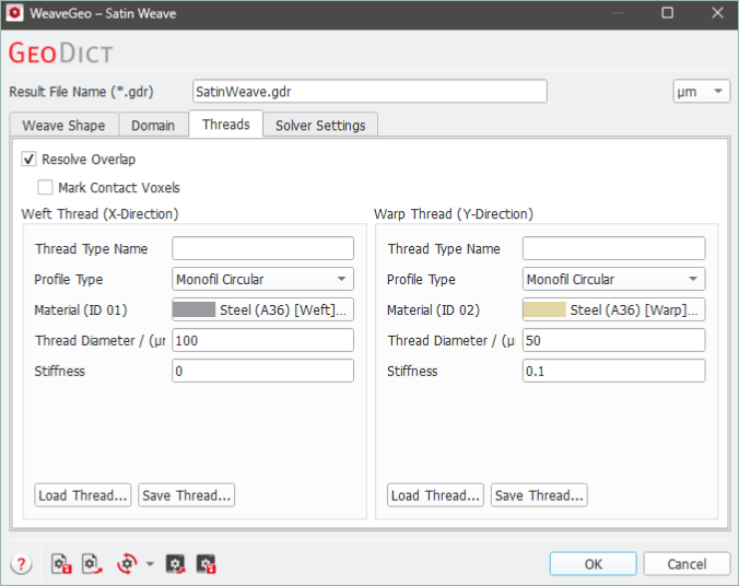
This tab is divided into three main parts. At the top select how overlapping threads should be treated. Below, there are two panels next to each other, one for the settings of the Weft Thread and one for the settings of the Warp Thread. Both contain the same parameters for the different thread types. Each thread can be modeled individually with different parameters.
Different threads might overlap in the generated structure, e.g., due to Vertical Thread Overlap (see Weave Shape tab). This might be unintuitive, but it leads to realistic thread shapes at contact points. Therefore, the thread overlap allows to create realistic weave structures without the need for simulating the physical effect of the thread contacts. By default, Resolve Overlap is enabled. With this option, the overlapping regions are assigned to the materials of the threads which are in contact. This leads to a more realistic structure. 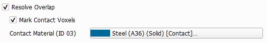 Additionally checking Mark Contact Voxels allows to define a separate material for the contact areas. This means, for each overlapping object a one voxel thick layer is reassigned to the Contact Material. In this way, even contacting threads with the same material ID can be clearly distinguished.
Alternatively, an Overlap Material can be selected for the regions where threads overlap. 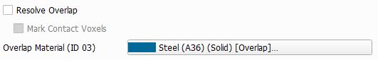 In the figure below, observe the effect of Resolve Overlap, Resolve Overlap with Mark Contact Voxels, and the use of an Overlap Material. The vertical thread overlap was set to 30 µm, while the threads have a height of 100 µm. |

 Can I save and reload settings for a thread?
Yes, this is possible. At the bottom of the Weft and the Warp Thread panel, respectively, there is a Save Thread button. Click it to enter a name and save the parameters to a *.gps file. This is a GeoDict settings file. 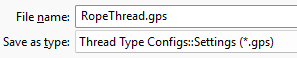 Previously saved threads can be imported by clicking Load Thread. |
Thread panels
Parameters for all profile types
In the Thread Type Name field, a name can be given to the warp or the weft thread generated with the current parameters, respectively. The name is not shown in the generated structure, only in the dialog. Giving the thread a name can support to easily recognize a loaded thread in the dialog. |
Seven Profile Types for the threads can be selected from the drop-down menu. 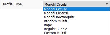 Monofil threads can have a Circular, Elliptical, or Rectangular cross-section. For the Multifil threads, Random Multifil and Custom Multifil are available. See the Thread Profile types section for explanations on Monofil, Multifil, Rope, and Regular Bundle profile types. |
For all profile types, Material determines the material assigned to the thread. Also the Material ID is given here. The Weft Thread has always Material ID 01, and the Warp Thread is always assigned to Material ID 02. Click on the material name to open the Material Selector and select the material for the corresponding thread from the GeoDict Material Database. |
Thread Width / Thread Height / Thread Diameter
Thread Width and Thread Height determine the size of the cross-section area of the thread. The thread height is the extent in Z-direction. As the weft thread has its longitudinal direction in X-direction, the thread width determines the extent in Y-direction. For the warp thread the thread width determines the extent in X-direction.
In case of a Monofil Circular profile type, width and height are equal, so only the Thread Diameter can be entered. |

The Stiffness parameter controls the bending behavior of the threads. A high stiffness indicates a rigid thread that only bends in small angles. Values for stiffness can vary from 0 to 1. This option only has an effect on plain weaves when using the FreeWeave Solver (in the Solver Settings tab). Below, an example of a plain weave is shown, where the Stiffness of the weft thread was varied. For the twill weave (shown below) and the satin weave the stiffness can also be modeled with the Classic WeaveGeo solver. Again, the Stiffness of the weft thread was varied. |
Parameters for Random Multifil, Rope, and Regular Bundle
For the profile type Rope, one of the predefined Rope Types must be selected from the drop-down menu. The selected Rope Type determines the filament Number which cannot be changed manually. In the example below, the warp thread is a 1x7 rope. This means that it consists of one strand which contains 7 filaments. Thus, the filament number is set to 7. The weft thread is a 3x3 rope, made of 3 strands of 3 filaments, which sets 9 as the filament number. The number of Unit Cells in warp and weft direction (under the Domain tab) was set to 2. |
For Random Multifil profile types, an arbitrary number of filaments can be entered. The upper limit is 10,000 filaments, but keep in mind that more filaments will lead to longer structure generation times. |
Enter the Number specifying the number of filaments per thread in regular bundles. Possible values are in the range from 1 to 19. |
Under Diameter enter the diameter of the individual filaments, which are all equal sized. |
Length of Lay is only available for Random Multifil and Rope. It gives the distance (in the chosen unit) that is needed for the thread to perform a full 360° rotation around itself (twist). Since a unit cell must be periodic, the Length of Lay must be chosen accordingly. This means that in general the size of a unit cell must be a multiple of the length of lay. This ensures that the thread makes an integer number of 360° rotations. It is also possible to make, e.g., only 180° twists if the filaments of the thread are arranged in a way that the structure stays periodic in the unit cell. If the entered length of lay does not allow to generate the unit cell periodically, a warning message appears, and the parameter is adjusted automatically. The choice of unrealistically short values might lead to artifacts in the generation and, therefore, to unrealistic structures. If the Length of Lay is set to zero, the filaments are not rotated around themselves. For ropes with several strands (here, the weft thread), the Length of Lay 1 is the length for one rotation of the rope (thread) and Length of Lay 2 is the length for one rotation of the strands in the rope. |
Direction of Rotation is only available for Random Multifil and Rope and sets the direction - right (Z-twist rope) or left (S-twist rope) - in which the thread is rotated around itself (here, the warp thread). It only has an effect if the value for Length of Lay is larger than zero. Direction of Rotation 1 controls the direction of rotation of the strand corresponding to Length of Lay 1: right (Z-twist strand) or left (S-twist strand). Direction of Rotation 2 controls the direction of rotation of the strand corresponding to Length of Lay 2. |
Lateral Oscillation is only available for Random Multifil threads. It is the degree of random waviness of the filaments in the X-Y-plane. A different structure with the same Lateral Oscillation can be generated by changing the Random Seed (see Weave Shape tab). |
Parameters for Custom Multifil
How does the Custom Multifil profile type work?
For Custom Multifil, the settings panel is structured hierarchically. On the first, layer the settings for the whole thread can be made. On the subsequent layers, the strands and filaments of which the thread is composed can be defined individually. At the bottom, the Thread Width and Thread Height are displayed. They cannot be edited since they are computed from the settings of the single filaments. The Stiffness is given for the whole thread. On each layer the parameters Diameter, Length of Lay, Direction, and Child Count are shown. The active parameters depend on the level of the corresponding filament. The Diameter is only editable for the filaments with a Child Count of 0 and defines their thickness. The diameter of the filament in the layer above is automatically computed based on the number of child filaments and their entered diameters.
Length of Lay and Direction are the same as described above and define how a filament is twisted around itself. They are only active if Child Count is not zero. Child Count defines in how many sub-filaments a filament is divided. The settings panel for each filament is displayed indented on the next layer. You can fold all lower layers by clicking on the small black triangle. Below, a Custom Multifil structure is shown, generated with the shown settings. The domain length in X- and Y-direction is 300 voxels, respectively. The weft thread consists of two right (Z)-twisted filaments and a single, thinner filament twisted left (S) around them. The warp thread consists of 4 filaments with different diameters which are also twisted. |
Special parameters for the FreeWeave solver
If the FreeWeave Solver is chosen (in the Solver Settings tab), an additional option at the bottom of the thread panels is available. Check Simulate Individual Filaments to simulate interactions between the single filaments. Setting Inner Stiffness to a non-zero value allows you set a filament stiffness value, that is different to the one of the whole thread. When Inner Stiffness is set to zero the regular Stiffness value for the thread is used. When Simulate Individual Filaments is not active, the thread is modeled as a single circular thread. Then the filaments are placed at their computed positions. The structure in the following example was produced with the shown settings. Observe the difference in the placement of the weft threads for Simulate Individual Filaments checked and unchecked. Simulate Individual Filaments is always available in the Complex Multi-Layer Weave command if a multifilament profile type is selected. |
©2026 created by Math2Market GmbH / Imprint / Privacy Policy