The Generate Granular Twin From 2D uses the Generate Granular Structure app to generate a digital twin of a 2D reference structure, combined with an optimization algorithm to iterate the twin to the target.
Know how! The Nelder–Mead method is a direct search method (based on function comparison) to find the minimum of an objective function in a multidimensional space. The method approximates a local optimum of a problem with n variables when the objective function varies smoothly and is unimodal. The method uses the concept of a simplex, which is a special polytope of n + 1 vertices in n dimensions. In each iteration, it extrapolates the behavior of the objective function measured at each test point in order to find a new test point and to replace one of the old test points with the new one. See the Wikipedia page and Brownlee, 2021 for further details.
In each iteration step of the optimization method, a structure is generated based on the optimization parameters and a scalar-valued error function is evaluated. For this, the generated structure is analyzed, and the results are compared with reference values from the reference structure.
Modules needed to run this GeoApp:
GrainGeo, PoroDict+MatDict, GeoApp-2Dto3D
Clicking Edit... opens the Generate Granular Twin From 2D dialog. At the top, define a Result File Name for the result file and the result folder containing the generated structure.
Select GlobalOptimizer to run a global optimization to find good initial parameters for the local optimizer. In this case, only the selections made in the Grain Generator, Random Field and Add Binder drop-down menus are complied with. The parameter values entered in the Overlay Grains and Random Field Settings, Grain Generator, Random FieldandAdd Binderpanels, e.g., for diameters and correlation lengths are not taken into account. Rather, the global optimizer tries to find good values for these parameters.
In this panel you setup the initial structure for the local optimization.
The Overlay Strength is the field overlay strength in percentage. At 100% overlay strength the result will only show the grain package, while at 0% overlay strength the result will show only the Gaussian random field. If no Random Field is used, this value is automatically set to 100%. If no Grain Generator is used, this value is automatically set to 0%.
Select the basic shape used to generate the 3D structure. Select None as Grain Generator to use only the Random Field for the structure generation. The app uses the GrainGeo - Create Grains command to create the grain structure. Be aware that all lengths are given in the unit voxel.
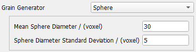
For the Sphere shape, the diameters are Gaussian distributed. Select the mean diameter and the standard deviation.
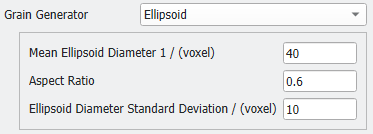
For the Ellipsoid shape, the first diameter is Gaussian distributed. Select the mean diameter and the standard deviation. For the other two diameters, the same fixed aspect ratio is used. The selected aspect ratio must be between 0.25 and 1. Therefore, only prolate spheroid shapes are possible here.
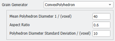
For the Convex Polyhedron shape, an (prolate spheroid) ellipsoid is used as enclosing object with matching Enclosing Object Volume (see the GrainGeo user guide for details). Select the mean diameter and the standard deviation. For the other two diameters, the same fixed aspect ratio is used. Again, the selected aspect ratio must be between 0.25 and 1.
The values entered for diameters, standard deviations and aspect ratios define the initial structure for the local optimization. They are only used if UseManual was selected for Initial Parameter Values.
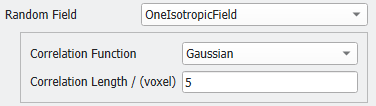
Enter the Correlation Length for the selected random field
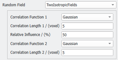
Select TwoIsotropicFields to use the GrainGeo - Stochastic Field Thresholding command to create a random field with the Custom Generation Option using two kernels. You can define the Relative Influence of the first kernel, select a Correlation Function for each kernel and give both Correlation Lengths.
The values entered for correlation length(s) and relative influence define the initial structure for the local optimization. They are only used if UseManual was selected for Initial Parameter Values.
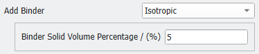
It is possible to use GrainGeo - Add Binder as an additional structure generation step. Select Isotropic and enter the desired Binder Solid Volume Percentage.
This function does not add another 'binder' material to the structure. Instead, it fills the small pores between the generated grains with the same material, thus creating a well-connected solid phase from unconnected objects. The added material isotropic and homogeneously distributed inside the structure.
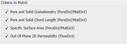
The error function is a combination of several components. Define the error function components from the list of physical properties. These structure properties will be matched by the twin as good as possible.
Select Specific Surface Area to use the MatDict - Estimate Surface Area command to compare the digital twin with the original 2D image.
Select Out-Of-Plane 2D Permeability to use the FlowDict - Stokes command to compare flow simulation results on a 2D slice with the original 2D image. The flow is computed in orthogonal (normal) direction to the 2D image plane with periodic boundary conditions. This corresponds to a 3D structure with parallel channels as illustrated below. Be aware that the computed 2D permeability is not comparable to the permeability of the 3D structure. This criteria is well suited as a supplementary matching criteria, because it alone exhibits a quadratic relationship on the pore radius size.
You must select at least one of these criteria, otherwise the optimizer will fail with an error message during the first optimization step.
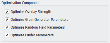
Select the sets of parameters to be used as optimization variables for fitting the reference structure. If not selected, the according parameters from the Digital Twin Setup will stay constant during the optimization.
Select Optimize Grain Generator Parameters to vary the diameter, standard deviation and aspect ratio parameters of the Grain Generator. Note that the optimizer does not optimize the generator type, i.e., does not vary between Sphere, Ellipsoid and ConvexPolyhedron shapes.
Select Optimize Random Field Parameters to vary the correlation length(s) and the relative influence parameters of the Random Field. Note that the optimizer does not vary between the OneIsotropicField and TwoIsotropicFields models.
Select Optimize Binder Parameters to vary the solid volume percentage of the binder.
You must select at least one of these options, otherwise the optimizer will fail with an error message.
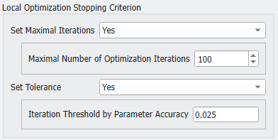
Set the stopping criterion by choosing a maximal number of iterations or set a tolerance accuracy to reach. Note that choosing none or setting the Maximal Number of Optimization Iterations to 0 will perform one single iteration step only.
The selected tolerance applies to the structure generation parameters varied in each iteration step. If the change in these parameters becomes smaller than the selected tolerance, the optimizer stops. The tolerance does not set a limit value for the resulting error function of the found digital twin.
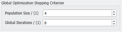
The Population Size is the number of random samples taken per parameter within the parameter bounds. A large value improves the exploration but increases the runtime for the Differential Evolution. The minimal value allowed is 2.
Global Iterations are the maximum number of generations to evolve the population in the Differential Evolution. Higher values refine the results but require more evaluations. The minimal value allowed is 2.
In total, the number of function evaluations can be up to Population Size times Global Iterations times the number of parameters. The number of parameters is defined by the selected Optimization Components.
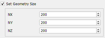
Activating the check box enables to set several additional parameter.
Check Invert Grains for Overlay to switch pore and solid material. In this case, the grain generator creates the pore space, and the background becomes the solid material.
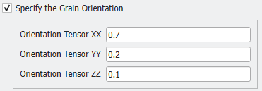
Each granular object is created with a random orientation. By default, the orientation is isotropic, and every direction has the same probability. Check the Specify the Grain Orientation box to define an anisotropic distribution of the object's orientation.
Define the orientation tensor as described for the Object Options of the GrainGeo - Create Grains command. The three Orientation Tensor parameters entered here correspond to the diagonal entries of the orientation tensor.
The tensor describes the distribution of the grain's main direction, which corresponds to the long axis of the prolate spheroid.
The created random field contains values distributed around mean value 0. Check Square Random Field to square these values, thus turning all values positive. Checking Invert Squared Field further inverts them. These operations fundamentally change the stochastic filed and the shape of the structures that appear after applying the threshold. See the Field Post-Processing in GrainGeo's Stochastic Field Thresholding command.
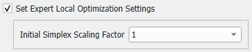
Increasing the step size of the local optimization may improve the results of the optimizer.
The structure generation is a stochastic process, therefore each test structure is not only dependent on the parameters to optimize, but also on a random number. The computed matching criteria are therefore dependent on the random number, too. If the dependency on the random number is larger that the dependency on the structure generation parameters, the local optimization may become stuck and cannot find the correct direction for the parameter search. Therefore, it may help to enlarge the step size to increase the effect of the parameter choice on the result and to help the algorithm find the new search direction.
Results
Click OK to input the entered parameters, and then click Run in the GeoApp section to start the app. The results are immediately shown in the opening Result Viewer after the process is finished.
Report tab
The Structure Details table reports the grid size, voxel length and solid volume percentage of the reference structure and the digital twin. The Digital Optimization Twin is the structure used for the comparison with the reference structure, the Digital Twin the created 3D structure.
The Structure Generation Parameters table shows the found optimal structure generation parameters. You can use these parameters as input in the Generate Structure app to create multiple digital twin models.
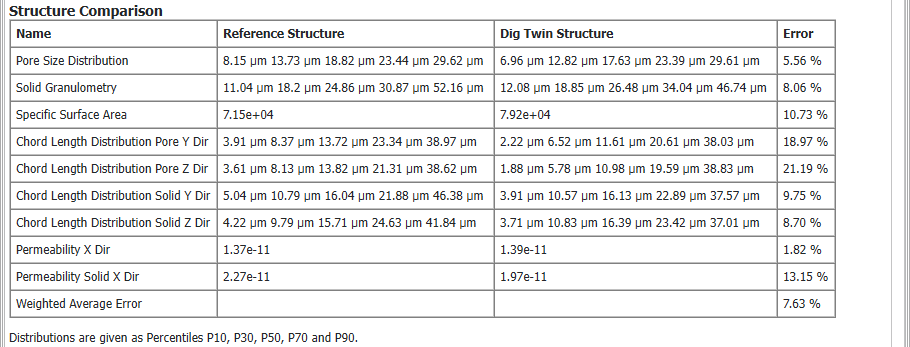
The Structure Comparison table compares the computed measures of the reference structure and the digital twin and states the error in the respective measure.
The Optimization table report the number of iterations and function evaluations needed. Below, the total runtime of the optimization is reported.
Plots tab
The Parameters by Evaluation and Parameters by Iteration plots show the evolution and convergence of the structure generation parameters in each step.
The Target Errors by Evaluation / Iteration plots show the results of the structure comparison in each step.
Data Visualization
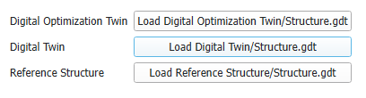
In this tab, you can load the 2D reference structure, the 2D Digital Optimization Twin used to compute the matching criteria and the created 3D Digital Twin.


 Overlay Grains and Random Field Settings